Pipe Extrusion Line Size Range: Why One Line Cannot Efficiently Cover Every Pipe Size
When buyers talk about pipe extrusion line size range, the misunderstanding rarely comes from extreme comparisons. Nobody is trying to run 1200 mm pipe on a small-diameter line. The real confusion happens in the overlapping middle ground — ranges like 16–75 mm, 50–160 mm, and 75–250 mm — where buyers look at a line recommended for 250 mm pipe and reasonably assume it should also handle 16 mm pipe just by changing the die. That assumption is wrong, and understanding why is what this article is about.
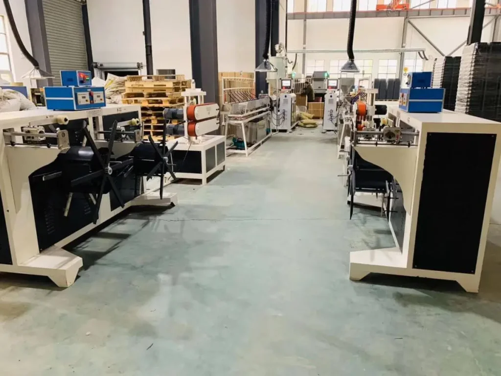
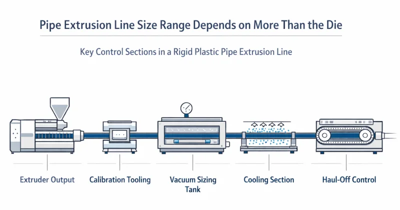
A die change may allow a different size to be produced. It does not automatically make that line stable, efficient, or economical across the full range. Real pipe extrusion line size range is defined by the overlap of several working windows at once: extruder output, calibration tooling, vacuum sizing, cooling, haul-off control, and finishing. When those windows align around the same size family, the line runs well. When they don’t, the pipe comes out — but not consistently, and not at acceptable quality or cost.
“You’re just trying to sell more equipment.”
This is the most common reaction — and it’s a fair one to raise. So let’s be direct about it.
We could sell you one line and tell you it handles everything. Some suppliers do exactly that. The pipe will come out. You’ll run a trial, it will look acceptable, and the purchase order will be signed.
What happens next is why we don’t do it.
Within a few months of real production, the problems begin — unstable wall thickness, dimensional drift, higher-than-expected scrap, quality complaints from your customers. At that point, you won’t think “I bought the wrong line configuration.” You’ll think “this equipment is garbage.” You’ll come back to us frustrated, and the reputation we’ve spent years building gets damaged by a sale we knew was the wrong fit from the beginning.
We would rather lose the order.
That’s not a noble stance — it’s a practical one. Our business depends on customers who come back, refer others, and trust our recommendations. A line that struggles in your production doesn’t just hurt you. It hurts us. So when we recommend a segmented configuration instead of a single wide-range line, it’s because we’ve seen what happens when the wrong match goes into production — and we’d rather explain the engineering upfront than manage the fallout afterward.
Maybe you’ll finish reading this and still think we’re just trying to upsell. That’s okay. There will always be suppliers willing to take that order. If it doesn’t work out the way they promised, we’ll still be here — and we hope the explanation in this article will make a little more sense by then.
Why This Misunderstanding Is So Common

The myth sounds reasonable because it contains a half-truth. Suppliers do sell one pipe extrusion line for multiple pipe sizes. Die heads (the tooling at the end of the extruder that shapes the melt into a pipe profile) are genuinely size-specific components. And in many factories, lines do run more than one diameter.
The confusion is that “multiple pipe sizes” in supplier documentation almost always means a defined family range — not unlimited downward flexibility. A line configured for 75–250 mm has its extruder output, calibration fixtures, vacuum tank capacity, cooling length, and haul-off speed range all matched to that band. Asking it to produce 16 mm pipe is not a question of die geometry. It is a question of whether every other subsystem can operate correctly at the conditions that 16 mm production actually requires — and the answer is usually no, or not well.
For more background on how a full extrusion system is structured, see [What Is a Plastic Extrusion Line? From Extruder to Full Production System].
The real question is never can this line make the pipe once. It is can this line make it well, repeatedly, and efficiently.
What Really Defines Pipe Extrusion Line Size Range
1. Extruder Output Window — Why Bigger Is Not Always More Flexible
Think of the extruder as the engine of the line. Every engine has a power band where it runs efficiently. Push it too far outside that band — too slow or too hard — and performance degrades.
Small-diameter pipe requires lower output, but that output must be more stable and finely controlled because small cross-sections have less tolerance for fluctuation. Large-diameter, thick-wall pipe requires high output and a completely different thermal balance. An extruder sized for one range pushed into the other doesn’t simply produce less efficiently — it can produce differently enough to affect product quality.
To put this in concrete terms: an SJ65/33 extruder is recommended for 16–75 mm rigid pipe. An SJ75/33 is recommended for 50–160 mm. An SJ90/33 is recommended for 75–250 mm. These ranges overlap at the edges, but each machine is built around a specific output zone, a specific screw geometry, and a specific downstream match. A buyer who selects the SJ90/33 expecting it to also run 16 mm production efficiently is asking the machine to operate far outside its designed output window — which means the screw runs too slowly, melt homogeneity suffers, and dimensional stability degrades.
Poor melt homogeneity is a direct cause of product dimensional variation — and low-RPM large-screw operation for small pipe is a reliable way to produce it. For a deeper look at how screw design and output stability interact, see Plastics Technology’s analysis of pressure control in single-screw extrusion.
Product consequences: wall thickness variation, unstable outer diameter, high startup scrap, disproportionate energy cost per kilogram of finished pipe.
2. Calibration Tooling — Why the Pipe Is Not Finished at the Die
When melt exits the die, it is still hot, still soft, and still dimensionally unstable. The die shapes the general profile. Final outer diameter, roundness, and surface quality are locked in by the calibration sleeve (a precision sizing tool matched to the target diameter) and the vacuum sizing tank downstream.
Each pipe size family requires matched calibration tooling. In practice, calibration sleeves are not universal across a broad rigid-pipe range, and changing diameter usually means changing the sleeve or changing to another tooling set designed for that OD band. When the calibration tooling is not properly matched to the target diameter, the die geometry becomes almost irrelevant: the pipe will not hold its shape correctly regardless.
Product consequences: outer diameter running outside tolerance, increased ovality, poor surface finish, extended startup scrap after each changeover.
3. Vacuum Sizing Tank — Why Physical Capacity Is a Hard Limit
The vacuum sizing tank is a sealed enclosure that uses negative pressure to hold the soft pipe against the calibration sleeve while it cools. Its internal dimensions set a hard upper limit on what pipe size it can process correctly — and no process adjustment changes that limit.
A tank built for small-diameter production does not become a large-pipe tank by adjusting parameters. The pipe either fits correctly within the sizing environment or it does not.
Product consequences: inadequate vacuum effect on the outer surface, weak outer diameter control, poor repeatability, degraded surface finish.
4. Cooling Capacity — Why Large-Pipe Problems Show Up After the Die
Cooling is where mismatched-line problems most often become visible. Thick-wall, large-diameter pipe carries substantially more heat and requires more cooling time to solidify. Heat must conduct from the inner wall outward through the full wall thickness, and that process can’t be rushed beyond what the material and geometry allow.
A small-pipe line cannot cool large-diameter pipe adequately. The pipe may still be soft when it reaches the haul-off, causing it to sag, deform, or change dimensions as it travels down the line.
Cooling tank length and water flow rate are calculated specifically for each pipe diameter and wall thickness — and these calculations are not interchangeable between line sizes. For a technical breakdown of how cooling capacity limits line output, see Plastics Technology’s analysis of maximizing cooling capacity in extrusion.
Product consequences: sagging before the wall solidifies, roundness degradation, wall thickness drift through the cooling section.
5. Haul-Off Control Range — Why “Can Pull It” Is Not the Same as “Can Control It”
The haul-off (the pulling unit that draws the pipe away from the die at a controlled speed) is part of dimensional control, not just material transport.
Haul-off speed directly affects average wall thickness — pulling faster draws the wall thinner, pulling slower allows it to build. For a detailed explanation of how this output–haul-off synchronization relationship works and how to monitor it during production, see our dedicated guide.
Small-diameter pipe typically runs at high line speeds. Large-diameter pipe runs very slowly. The speed ratio between the two ends of a broad claimed range can be dramatic, and a haul-off optimized for one end may not maintain the control precision needed at the other. Clamping pressure also matters: contact force must be matched to the pipe diameter and wall stiffness, or the haul-off will either mark thin-wall product or fail to grip heavy-wall large pipe adequately.
Product consequences: diameter drift during the run, wall thickness variation, surface marking from incorrect clamping.
A Better Way to Understand Overlapping Ranges

The most useful mental model is not “which sizes can this line theoretically produce” but “where do all five working windows overlap.”
Every subsystem has a range where it operates well. The extruder has an output zone where melt quality is consistent. The calibration tooling has a diameter it is built for. The vacuum tank has a physical capacity envelope. The cooling section has a heat removal rate matched to a wall thickness family. The haul-off has a speed and force range where control is precise.
When all five windows overlap around the same size family — say, 16–75 mm — that line is a genuine small-pipe line. When they overlap around 75–250 mm, that line is a genuine mid-range rigid pipe line. The mistake is assuming that changing one variable (the die) automatically moves all the other windows in step with it.
This is why line recommendations follow a segmented structure — SJ65/33 for 16–75 mm, SJ75/33 for 50–160 mm, SJ90/33 for 75–250 mm — and why the ranges overlap at the edges but are not interchangeable. The overlap at the boundary means a line can stretch slightly into adjacent territory. It does not mean the whole range of the larger line is available to the smaller product, or vice versa.
What the market calls flexibility is segmented flexibility — not universal capability.
What Buyers Should Ask Before Accepting a Wide-Range Claim
The right question when evaluating a rigid pipe line is not “Can I change the die to run this size?” The right question is: “What is this line’s efficient operating range, and what must change — beyond the die — to run a different size within it?”
A complete answer should cover:
- The realistic OD range, with wall thickness assumptions at both ends
- The realistic line speed and output rate at both ends of the range
- What calibration tooling changes are required for each size
- What vacuum and haul-off settings change, and how
- What startup scrap is expected after a full changeover
- Whether the line has been run in sustained production — not just trial conditions — at the sizes being quoted
A supplier who can answer all of those questions specifically is describing a real production system. A supplier whose answer is “just change the die” is describing a theoretical possibility.
The safest buyer does not ask “Can this line make my pipe?” but “Can this line make my pipe well, repeatedly, and commercially?”
Conclusion
The real answer to pipe extrusion line size range is not found in the die. A pipe extrusion line is defined by the overlap of its output window, calibration system, vacuum tank capacity, cooling capacity, and haul-off control range. When those windows align around a size family, the line produces that family well. When they don’t, production is possible but not reliable.
A line recommended for 75–250 mm is not automatically a good 16 mm line. A broad claimed range is not automatically a strong production choice. What matters is whether the whole system is matched to the product family you actually need to run — not whether a die head can be physically installed.
FAQ
Q1: Can one pipe extrusion line run different diameters?
Yes, but usually within a defined family range. The practical limitation is not the die alone. It is whether output, calibration, vacuum sizing, cooling, and haul-off control remain properly matched across that range.
Q2: Why is a pipe extrusion die change not enough by itself?
Because final pipe quality depends on the calibration sleeve, vacuum sizing, cooling, and haul-off — all of which must also be matched to the target diameter. Changing the die changes the melt exit geometry. It does not change any of those downstream conditions.
Q3: Why can a larger line be a poor choice for smaller pipe?
Because a larger line’s output window, cooling configuration, and haul-off speed range are matched to larger product. Running small pipe on a large line pushes the process outside its efficient zone, producing worse melt homogeneity, worse dimensional stability, and higher scrap — even if the pipe technically comes out.
Q4: What should I ask a supplier about pipe extrusion line flexibility?
Ask for the efficient operating range, not just the claimed range. Ask what changes besides the die, what downstream limits apply, what line speed and quality can be expected at both ends of the range, and whether the performance claims are backed by sustained production data or trial conditions only.
Have Technical Questions?
Our engineering team is ready to help with your extrusion process or machine configuration.
Jason Shen
Jason is the founder of Jinxin Extruder and a veteran engineer with over 20 years of hands-on experience in plastic machinery.
Starting his career on the shop floor, he mastered every technical detail—from electrical wiring to complex troubleshooting.
Today, he personally oversees final inspections, ensuring every machine is built with deep technical expertise and field-tested reliability.
Further Reading
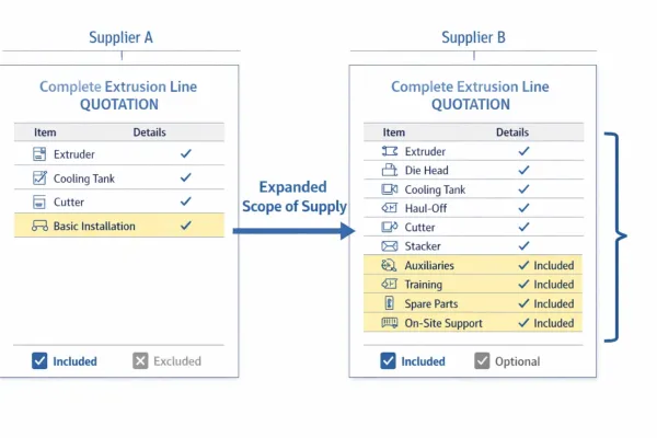
Extrusion Line Quotation: What Is Included and What to Check Before You Buy
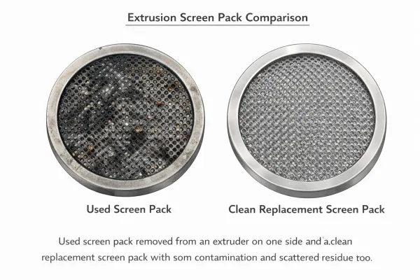
Comparing extrusion line quotations? Use this scope of supply checklist to see what is included, what is typically excluded, and…Extrusion Screen Changer & Melt Filtration: How to Reduce Contamination and Pressure Fluctuation
A practical guide to screen changers in plastic extrusion — how melt filtration controls contamination, why screen changes cause pressure…