Extrusion Output and Haul-Off Speed: How Line Synchronization Controls Product Dimensions
Lede
Extruder output and haul-off speed synchronization is the control relationship that determines wall thickness, outer diameter, and cross-section geometry in plastic extrusion. When these two sides of the line are properly matched, dimensions stay stable. When they are not, dimensional problems follow — regardless of how well each individual machine is performing on its own.
Quick Answer:
Extruder output and haul-off speed synchronization is the condition in which material delivery and product removal are matched — producing stable wall thickness, OD, and cross-section geometry. The quantitative link is the draw-down ratio (DDR = die exit area ÷ final product area). When DDR shifts — because either side changed — dimensions change immediately.
Maintaining synchronization requires coordinated adjustment of both sides and monitoring of meter weight trend, melt pressure, and wall thickness as leading and lagging indicators. If you are already seeing dimensional drift, the diagnostic starting point is: Is meter weight stable or changing? Stable meter weight with drifting dimensions points downstream. Changing meter weight points to the output–haul-off relationship or upstream.
In this article, you will learn:
- What output–haul-off synchronization actually means in extrusion, and why it is a control relationship rather than a speed setting
- How the draw-down ratio connects extruder delivery and haul-off pull into a single measurable variable
- What happens to wall thickness and OD when this relationship shifts — and why the effect is immediate
- Why line speed changes are not neutral — and how long you need to wait before the line reaches a new steady state
- How to monitor and maintain synchronization during production, including what signals to watch and in what order
- Where synchronization ends and broader troubleshooting begins
1. What Is Output–Haul-Off Synchronization?
Output–haul-off synchronization is the condition in which the mass of material the extruder delivers per unit time is matched to the rate at which the haul-off removes product from the shaping section — resulting in stable dimensions at the target geometry.
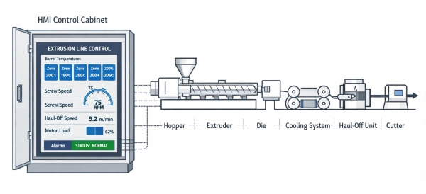
This is the foundational control relationship in any continuous extrusion line. The extruder pushes melt through the die at a volumetric rate determined by screw speed, melt viscosity, and head pressure. The haul-off pulls the shaped product forward at a linear speed set by the operator or control system. Between these two forces, the product’s final cross-section is determined.
When the two sides are matched, every meter of product receives the same amount of material. When they are not matched, the material per unit length changes — and the geometry changes with it.
This sounds simple, but it is not a one-time setting. Output rate shifts with melt temperature, material batch variation, feeding stability, and screw condition. Haul-off behavior shifts with grip condition, belt wear, and load. Synchronization is a running condition that must be maintained, not a parameter that can be set and forgotten.
For operators unfamiliar with how the full extrusion production line works as an integrated system, this is the single most important interaction to understand: the extruder and the haul-off are not independent machines. They are two halves of the same dimensional control mechanism. The downstream equipment — calibration, cooling, cutting — can only stabilize what the output–haul-off relationship has already defined.

2. Draw-Down Ratio: The Variable That Connects Both Sides
Draw-down ratio (DDR) is the quantitative expression of the output–haul-off relationship. It tells you how much the product is being stretched — or not — between die exit and final sizing.
Definition: Draw-down ratio is the ratio of die exit cross-sectional area to the final product cross-sectional area after cooling and sizing.
DDR = A_die / A_product

Where:
- A_die = cross-sectional area of the melt at the die exit
- A_product = cross-sectional area of the cooled, sized product
A DDR of 1.0 means the product has the same cross-section as the die opening — no stretching, no compression. In practice, most extrusion processes operate with DDR > 1.0, meaning the haul-off is pulling the product slightly faster than the natural exit speed of the melt. This controlled stretch is what reduces the product from die size to target size.
Why DDR matters for operators:
DDR is not an abstract number. It is the direct link between your speed settings and your product dimensions:
- Higher DDR (haul-off relatively faster): thinner wall, smaller OD, less material per meter
- Lower DDR (haul-off relatively slower): thicker wall, larger OD, more material per meter
- Unstable DDR (either side fluctuating): dimensional variation — the wall changes even though no one touched a setting
The critical point is that DDR changes whenever either side changes. An operator who increases screw RPM without adjusting haul-off speed has changed the DDR. An operator who increases haul-off speed without confirming that output has followed has also changed the DDR. Both actions move the product geometry, even if only one machine was adjusted.
For pipe extrusion under standards such as ISO 4427-1, dimensional tolerances are narrow enough that a DDR shift of a few percent can move wall thickness outside specification. This is why DDR awareness — not just speed awareness — is essential for any operator running dimensionally critical products.
3. What Happens When Synchronization Is Lost
Loss of synchronization changes the material per unit length — and the product geometry responds immediately.
The effect has two directions:
Overdraw (haul-off effectively ahead of output): wall thickness decreases, OD may shrink, meter weight drops.
Overfeed (extruder delivering more than haul-off removes): wall thickness increases, product may sag or deform between die and sizing.
The critical point is that these are not separate faults on separate machines. They are two expressions of the same mismatch — and correcting only one side without confirming the stability of the other often makes the problem worse rather than better.
If you are already seeing wall thickness drift, fluctuation, or directional change during production, the structured diagnostic path — including how to distinguish drift from fluctuation, how to identify which side is causing the imbalance, and step-by-step correction for each pattern — is in our guide to extrusion wall thickness variation: causes, diagnosis, and correction.
The remainder of this article focuses on the control side: why speed changes shift the synchronization relationship (Section 4), how to maintain synchronization through coordinated control and monitoring (Section 5), and where synchronization problems end and broader system issues begin (Section 6).

4. Why Line Speed Changes Are Not Neutral
Changing line speed changes the synchronization condition. This is the single most overlooked operational fact in extrusion.
When an operator increases haul-off speed to raise output, the extruder must deliver proportionally more material to maintain the same DDR. But extruder response is not instantaneous. Screw output depends on melt viscosity, which depends on temperature, which depends on residence time — all of which shift when speed changes. The system needs time to reach a new steady state.
During this transition period, the DDR has changed even though the operator intended to maintain it. The wall is thinner, the meter weight is lower, and the product may be out of spec — until the extruder catches up (if it can).
What we see in production: On rigid pipe lines running PE or PP, a 10% haul-off speed increase without coordinated extruder adjustment typically produces a measurable wall thickness reduction by the time the affected product reaches the downstream gauge — usually within the first 5–10 meters of product after the change, depending on line layout and gauge position. On lines with a meter weight control system, this deviation is caught and compensated automatically. On manually controlled lines, it depends entirely on the operator noticing the change — which often does not happen until the next measurement cycle.

The practical rule: Any speed change on one side of the line requires a coordinated response on the other side, followed by a stabilization period before the new condition can be trusted. Operators who change speed and immediately check dimensions are measuring a transition, not a steady state.
5. Coordinated Control: How to Think About Synchronization
Synchronization is not about matching two numbers. It is about maintaining a stable material-per-unit-length condition across the entire operating range.
5.1 Manual lines: The operator is the control loop
On lines without automatic feedback, the operator is responsible for maintaining synchronization. This means:
- After any speed change, wait for the line to stabilize before judging the result. On most pipe lines, this takes 3–5 minutes of steady running — not 30 seconds
- Monitor meter weight or wall thickness as the primary indicator, not just RPM and line speed readouts. RPM tells you what the screw is doing; meter weight tells you what the product is actually receiving
- When adjusting, change one parameter at a time and wait for the system to respond. Simultaneous changes to screw speed and haul-off speed make it impossible to identify which adjustment had what effect
5.2 Lines with gravimetric feedback
A loss-in-weight meter weight control system closes this loop automatically. It measures actual material consumption and adjusts screw speed or haul-off to maintain target weight per meter. This removes the operator’s reaction time from the equation and compensates for material variation, thermal drift, and feeding inconsistency in real time.
On lines with gravimetric control, synchronization becomes a system property rather than an operator skill. This is one of the main reasons Jinxin includes meter weight control as standard on rigid pipe and profile lines where dimensional tolerances are tight.
5.3 The monitoring framework
Whether manual or automatic, the key signals to watch for synchronization health are listed below — ordered from most direct to most indirect:
| Signal | When stable | When drifting | Response characteristic |
|---|---|---|---|
| Meter weight trend | Synchronization is holding — material per meter is consistent | The output–haul-off relationship has shifted | Most direct indicator — measured at the feed system in real time |
| Melt pressure at die inlet | Extruder delivery is consistent | Something has changed at the extruder or upstream of it | Leading indicator — pressure reflects screw behavior before the effect reaches the product downstream |
| Wall thickness trend | Dimensions are on target | Synchronization has already shifted | Lagging indicator — the gauge is located meters downstream from the die; by the time it registers a change, multiple meters of affected product have already been produced |
| Haul-off motor current | Load is normal | Pulling resistance or product characteristics may have changed | Indirect indicator — does not measure synchronization directly, but a load anomaly may signal grip loss, product stiffness change, or downstream obstruction worth investigating |

Operators who watch trends rather than single-point readings catch synchronization problems before they produce scrap. A wall measurement that says “4.1 mm” is a fact. A wall trend that shows “4.1 → 4.0 → 3.9 over the last 20 minutes” is a warning.
6. Where Synchronization Ends and Broader Troubleshooting Begins
Synchronization explains one category of dimensional problems: those caused by a mismatch between output and haul-off.
But not all dimensional problems come from synchronization. If the output itself is unstable — due to feeding inconsistency, melt temperature fluctuation, screw wear, or contamination — the line may be perfectly “synchronized” in terms of speed settings, yet still produce unstable dimensions. In that case, the real problem is upstream, and no amount of haul-off adjustment will fix it.
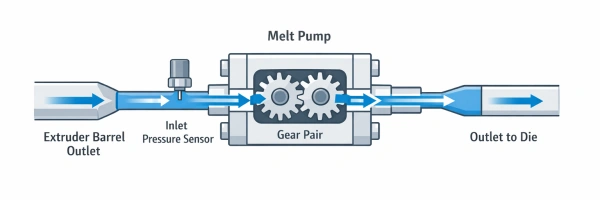
When the instability is caused by screw output fluctuation and tolerances are tight, a melt pump may be the appropriate next step — but only after confirming the problem is metering-related and not a melting or feeding issue.
Similarly, if the cooling or calibration section is not functioning consistently — unstable vacuum, uneven water temperature, worn sizing sleeves — the product may leave the synchronization zone in good condition and still arrive at the cutter out of spec. In that case, the real problem is downstream.
The diagnostic question is always: Is the material per unit length stable, or is it changing?
- If meter weight is stable but dimensions are still drifting → the problem is downstream (cooling, calibration, sizing)
- If meter weight is changing → the problem is in the output–haul-off relationship or upstream of it (feeding, melting, screw condition)
When dimensional problems appear together with feeding issues, surface defects, or temperature instability, the situation has moved beyond synchronization into system-level troubleshooting. For that broader diagnostic path, see our guide to dimension drift and wall thickness variation diagnosis.
FAQ
1. What is the draw-down ratio in plastic extrusion?
Draw-down ratio (DDR) is the ratio of the die exit cross-sectional area to the final product cross-sectional area. It quantifies how much the product is stretched between the die and the sizing section. A higher DDR means more stretch and thinner product; a lower DDR means less stretch and heavier product. DDR is controlled by the relationship between extruder output rate and haul-off speed.
2. Why does wall thickness change when I increase line speed?
Because increasing haul-off speed without a proportional increase in extruder output changes the draw-down ratio. The product receives less material per unit length and the wall becomes thinner. The extruder needs time to reach a new stable output level after any speed change, so there is always a transition period during which the wall is not at target.
3. Can I fix wall thickness by adjusting only the haul-off speed?
In some cases, yes — if the extruder output is stable and the problem is purely a speed mismatch. But if the output itself is unstable (due to feeding variation, melt temperature drift, or screw wear), adjusting only the haul-off creates a moving target. You must first confirm whether the output side is stable before correcting the haul-off side.
4. What is the difference between synchronization problems and wall thickness troubleshooting?
Synchronization refers to the control relationship between extruder output and haul-off speed — it is about understanding and maintaining the correct DDR. Wall thickness troubleshooting is broader: it includes synchronization problems, but also covers feeding instability, cooling issues, die flow distribution, and calibration problems. Synchronization is one cause; wall thickness variation is the symptom that may have multiple causes.
5. How does a meter weight control system help with synchronization?
A loss-in-weight meter weight control system measures actual material consumption in real time and automatically adjusts screw speed or haul-off speed to maintain target weight per meter. This closes the synchronization loop without depending on operator reaction time, and compensates for material variation, thermal drift, and feeding inconsistency automatically.
6. How do I know if my dimensional problem is a synchronization issue or something else?
Check meter weight. If meter weight is changing, the problem is in the output–haul-off relationship or upstream of it — feeding, melting, or screw condition. If meter weight is stable but dimensions are still drifting, the problem is downstream — cooling, calibration, or sizing. This single check prevents the most common misdiagnosis in extrusion troubleshooting: adjusting synchronization when the real cause is downstream instability.
7. Is draw-down ratio only relevant for die design, or does it matter during production?
Both. DDR is commonly discussed as a tooling design calculation — sizing the die opening relative to the target product dimensions. But it is equally important as a running production variable. Any change to screw speed or haul-off speed changes the effective DDR — and therefore changes product dimensions — even if the die has not been touched. Operators who think of DDR only as a die sizing number often miss the connection between speed adjustments and the dimensional shifts that follow.
Keeping Your Line in Balance
If you are seeing wall thickness drift, meter weight variation, or dimensional instability that appears after speed changes, the output–haul-off relationship is the first place to investigate. Tell us your product type, target dimensions, current line configuration, and when the problem appears during production. We can help you determine whether the issue is a synchronization mismatch, an upstream instability, or a downstream control problem — and what the most direct correction path is.
Have Technical Questions?
Our engineering team is ready to help with your extrusion process or machine configuration.
Have Technical Questions?
Our engineering team is ready to help with your extrusion process or machine configuration.
Jason Shen
Jason is the founder of Jinxin Extruder and a veteran engineer with over 20 years of hands-on experience in plastic machinery.
Starting his career on the shop floor, he mastered every technical detail—from electrical wiring to complex troubleshooting.
Today, he personally oversees final inspections, ensuring every machine is built with deep technical expertise and field-tested reliability.
Further Reading
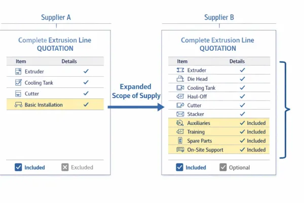
Extrusion Line Quotation: What Is Included and What to Check Before You Buy
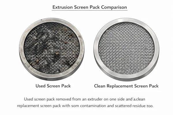
Comparing extrusion line quotations? Use this scope of supply checklist to see what is included, what is typically excluded, and…Extrusion Screen Changer & Melt Filtration: How to Reduce Contamination and Pressure Fluctuation
A practical guide to screen changers in plastic extrusion — how melt filtration controls contamination, why screen changes cause pressure…