What Is a Plastic Extrusion Line? How a Full Production System Is Built Around Your Product
A plastic extrusion line is not a single machine. It is a complete production system — from raw material feeding to finished product collection — engineered to continuously produce a specific plastic product at stable dimensions and consistent quality.
If you are unfamiliar with the extrusion process itself, start with What Is Plastic Extrusion?. If you want to understand the extruder — the central machine in any line — see What Is a Plastic Extruder Machine?. For a closer look at the equipment that comes after the extruder, see Downstream Equipment in Plastic Extrusion.
This article is about the line as a whole — not what each component does, but how and why a specific line configuration is determined by the product it needs to produce.

1. Every Line Is Reverse-Engineered from the Product
There is no such thing as a standard extrusion line. Every line is configured by working backward from what the customer needs to produce: the material, the cross-section, the dimensional tolerances, and the required output rate. Each of these decisions drives the selection of a specific component — and those components must work together as a system.
Material determines the screw
The extruder screw is the first component to be defined, and it is determined primarily by the polymer being processed. Different materials have fundamentally different melting behavior, viscosity, and thermal sensitivity — and the screw must be designed to match.
The most important screw parameters are the compression ratio (the ratio of feed channel depth to metering channel depth) and the length-to-diameter ratio (L/D). These are not arbitrary — they are dictated by the physical properties of the polymer:
| Polymer | Compression Ratio | Typical L/D | Why |
|---|---|---|---|
| PE (Polyethylene) | 3–4 | 24–30:1 | Crystalline, thermally stable, flows easily — tolerates higher compression |
| PP (Polypropylene) | 3.5–4 | 24–30:1 | Similar to PE — good thermal stability, needs adequate compression for melting |
| Rigid PVC | ~2.5 | 20–24:1 | Extremely heat-sensitive — lowest thermal degradation activation energy among common plastics (20 kcal/mol vs. 46 for PE, 65 for PP). Poor thermal conductivity (0.19 W/mK, one-third of PE). Must use low compression to avoid degradation |
| PA (Nylon) | 3–3.5 | 18–20:1 | Narrow melting range, low viscosity, high flow — needs rapid-transition screw design. Hygroscopic — requires pre-drying |
| PC (Polycarbonate) | 2–3 | 20–22:1 | High viscosity, strongly hygroscopic — needs controlled compression and moisture management |
Compression ratio data: Kalshine, Lesun Screw. PVC thermal properties: Kanademy. Compression ratio fundamentals: Plastics Technology.
A screw designed for PE will not work properly for PVC — the compression is too aggressive for a heat-sensitive material. A screw designed for PA has a rapid-transition profile that would cause poor melting in PE. This is why extrusion screws are always specified for the target material, not selected from a generic catalog.
Product shape determines the die
The extrusion die is designed to match the target product cross-section. A pipe die produces an annular shape. A profile die produces a custom cross-section — which can be solid, hollow, or multi-chamber. The die geometry, flow channel design, and land length are all engineered for the specific product dimensions.
Product requirements determine the downstream
Everything after the die — sizing, cooling, haul-off, cutting, and collection — is selected based on what the product needs:
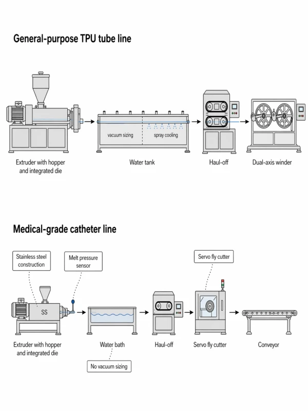
- A rigid pipe needs vacuum calibration to lock the outer diameter while the material is still soft. A flexible tube may need only a water bath — the material’s elasticity provides enough dimensional stability without vacuum.
- A complex profile needs calibration blocks — multiple internally water-cooled steel blocks that constrain the shape from all directions as it solidifies. A simple round pipe does not need this level of multi-directional constraint.
- A product sold in fixed lengths needs a precision cutter. A product sold in coils needs a winding system with tension control.
These are not accessories added to a standard machine. They are integral parts of the line, each selected because the product demands it.
2. Different Products, Different Lines — Even with the Same Material
The most common way to explain extrusion line differences is by product type: pipe lines, profile lines, sheet lines, tube lines. This is valid — the downstream equipment for a pipe line and a profile line is fundamentally different.
But there is a second layer that is often overlooked: the same material, processed into different products for different applications, results in completely different line configurations.
Layer 1: Product type defines line structure
Pipe line vs. Profile line — the sizing section is fundamentally different:
| Pipe Line | Profile Line | |
|---|---|---|
| Die | Annular die (round cross-section) | Custom profile die (complex cross-section) |
| Sizing | Vacuum sizing sleeve — negative pressure holds the soft pipe against a metal sleeve, controlling OD and roundness | Calibration blocks — multiple internally water-cooled steel blocks with vacuum ports, constraining the shape from multiple directions |
| Why different | Pipe is axially symmetric — a single sleeve provides uniform constraint around the circumference | Profile is asymmetric and often multi-chamber — requires multi-directional constraint during cooling |
| Cooling | Vacuum tank + spray cooling troughs | Internal water cooling in calibration blocks + downstream water tanks |
| Cutting | Chipless cutter or saw, tracking line speed | Saw cut, adapted to complex cross-section |
Both types use water cooling — the difference is not “wet vs. dry” but the structure of the sizing section. Pipes are sized by a single cylindrical sleeve inside a vacuum tank. Profiles are sized by a series of shaped metal blocks that match the profile’s cross-section.
Pipe sizing methods: Conair — Three Primary Types of Sizing Tooling. Profile calibration: Plastics Technology — How to Size & Calibrate Profile Parts. Pipe tooling selection: Plastics Technology — How to Select the Right Tooling for Pipe Extrusion.
3. Line Performance Depends on System Matching
Once the right components are selected, they must work together. An extrusion line is a continuous process — material flows from feeding to finished product without interruption. Any instability at one stage propagates downstream.
The critical chain is:
Feeding stability → Melt consistency → Output–haul-off synchronization → Cooling uniformity → Final product dimensions
- If feeding is inconsistent, the extruder output fluctuates — and every downstream measurement (wall thickness, weight per meter, OD) moves with it.
- If extruder output and haul-off speed are not synchronized, the draw-down ratio shifts and wall thickness changes — even if no one touched a setting.
- If cooling is uneven, the product may leave the sizing section in good shape but warp or deform afterward.
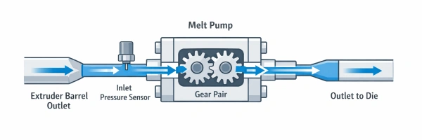
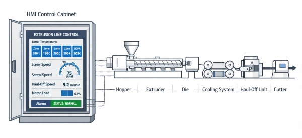
On lines running dimensionally critical products, closed-loop systems tie these stages together. A gravimetric meter weight control system measures actual material consumption and adjusts screw speed or haul-off to maintain target weight per meter — removing operator reaction time from the equation. A PLC-based control system coordinates temperatures, speeds, and pressures across the entire line from a single interface, with recipe storage so that validated settings can be recalled for repeat production runs. For products with the tightest tolerances, a melt pump provides an additional layer of output stability by mechanically decoupling die pressure from screw behavior.
The point is not that every line needs every control system. It is that the components of a line are not independent machines — they are parts of a single system whose performance is determined by how well they are matched to each other and to the product.
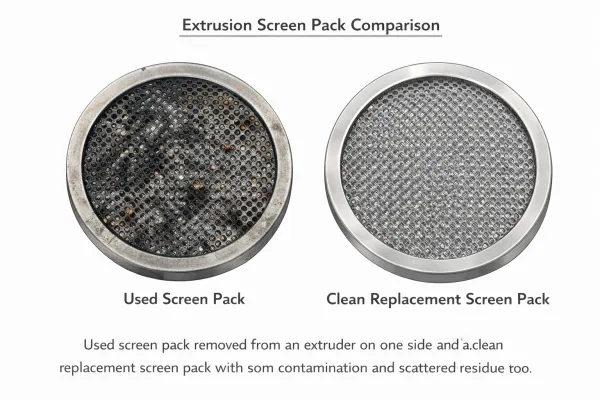
For lines running regrind or recycled material, an extrusion screen changer provides continuous melt filtration to protect product quality.
4. Factory Acceptance Test: Verifying Production Capability Before Delivery
A properly configured line is verified before it leaves the factory through a Factory Acceptance Test (FAT). The purpose of FAT is straightforward: run the line, produce the product, and confirm that the die and downstream equipment deliver the customer’s target dimensions.
The design and calculation phase establishes the theoretical configuration. But theoretical design and actual production are never identical — die flow behavior, cooling rates, and sizing conditions in practice may differ from what was calculated. FAT is where these differences are identified and corrected.
How it works in practice
For standard materials — PE, PP, PVC, and similar commodity polymers — the test is run using the manufacturer’s own material. The global additive systems and formulation ratios for these polymers are well-established and consistent across suppliers, so the processing behavior is representative of what the customer will run in production.
For modified or compound materials — TPE, custom blends, or specialty formulations where the processing behavior depends on the specific compound recipe — the customer ships 10–20 kg of their actual production material to the factory. The FAT is then run with the customer’s resin to ensure the line performs correctly with that specific formulation.
What is being verified
The primary focus of FAT is die dimensional accuracy: can the die, calibration tooling, and downstream equipment produce the customer’s target product dimensions? This includes outer diameter, wall thickness, cross-section geometry, and surface finish.
If the dimensions are not within specification, the die or tooling is modified immediately — at the factory, where the engineering team and machining capability are on hand. This is the core value of FAT: problems are found and fixed before the line ships, not after it arrives at the customer’s facility.
5. Before Evaluating a Line: Five Things to Define First
If you are specifying an extrusion line — whether requesting a quotation, comparing suppliers, or evaluating a proposal — these are the five things that must be defined before the line configuration can be meaningful.
If you are specifying an extrusion line — whether requesting a quotation, comparing suppliers, or evaluating a proposal — these are the five things that must be defined before the line configuration can be meaningful.
1. Product drawing or sample — The exact cross-section geometry with dimensions and tolerances. For pipes: OD, wall thickness, and tolerance band. For profiles: a complete cross-section drawing. For tubes: ID, OD, and wall thickness.
For multi-layer products (co-extrusion): the wall thickness of each individual layer, not just the total. Each layer is produced by a separate extruder through a dedicated flow channel in the co-extrusion die. Layer-by-layer dimensions determine how many extruders are needed, how each one is sized, and how the die is designed.
Beyond geometry, layer thickness also affects mechanical properties — pressure resistance, barrier performance, and bonding strength between layers.
If you are unsure about layer distribution, a qualified manufacturer can provide reference recommendations. But the starting point is always your target product sample or specification, not the manufacturer’s assumption.
2. Material — The specific polymer and grade. PE100 and PE80 are different. Rigid PVC and flexible PVC require different screw designs. A TPE compound with 30% filler processes differently from a neat TPU. If you are using a modified or specialty material, have the datasheet ready.
3. Dimensional tolerances — The acceptable range for your critical dimensions. This determines the level of sizing, monitoring, and control required. A ±0.1mm wall tolerance requires different equipment than ±0.5mm.
4. Output rate — How many kilograms per hour or meters per minute you need. This determines extruder size, motor power, cooling length, and downstream speed capacity.
Be realistic: output rate is constrained by the product itself. Thicker walls need longer cooling time. Complex profiles need slower line speeds for stable calibration. For precision-critical products — such as medical tubing or tight-tolerance profiles — dimensional accuracy must take priority over speed. Higher output generally means less time for cooling and sizing, which reduces dimensional stability.
If you request a speed that exceeds what the product geometry and material can physically support, the line would require disproportionately longer cooling sections — or simply cannot deliver stable quality at that rate. A qualified manufacturer will help you find the practical balance between output and precision for your specific product.
5. Delivery form — How the finished product leaves the line: cut to fixed lengths (and what lengths), coiled (and what coil size/weight), or wound on spools. This determines the cutting, stacking, winding, and packaging equipment at the end of the line.
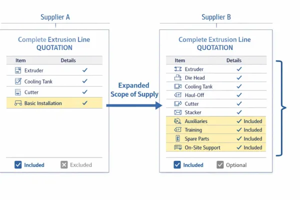
For a detailed framework on comparing quotations once you have these defined, see our Extrusion Line Quotation Checklist.
FAQ
What is the difference between an extrusion line and an extruder?
An extruder is a single machine that melts and pushes plastic through a die. An extrusion line is the complete production system — extruder, die, sizing equipment, cooling, haul-off, cutting or winding, and all auxiliary equipment — required to continuously produce a finished product. The extruder is one component of the line.
Why can’t I use the same extrusion line for different products?
Because the screw, die, sizing equipment, cooling system, and cutting method are all selected for a specific material and product geometry. A screw designed for PE has the wrong compression ratio for PVC. A vacuum sizing tank designed for rigid pipe cannot calibrate a complex profile. Some components (like the extruder) may be reused across products with tooling changes, but the downstream equipment is typically product-specific.
What determines the cost of an extrusion line?
The main cost drivers are extruder size (screw diameter and motor power), the complexity of the die and sizing tooling, the length and type of cooling equipment, the level of automation and control, and any special requirements such as servo drives, inline measurement, or cleanroom-compatible construction. Two lines producing the same type of product can differ significantly in cost depending on the dimensional tolerances, output rate, and application requirements.
What is a Factory Acceptance Test (FAT) and why does it matter?
A FAT is a production test run at the manufacturer’s factory before the line is shipped. Its purpose is to verify that the die and downstream equipment produce the customer’s target product dimensions. Because design calculations and actual production always have some differences, FAT identifies and corrects these differences while the engineering team and machining tools are still available — avoiding costly adjustments after installation at the customer’s site.
Have Technical Questions?
Our engineering team is ready to help with your extrusion process or machine configuration.
Jason Shen
Jason is the founder of Jinxin Extruder and a veteran engineer with over 20 years of hands-on experience in plastic machinery.
Starting his career on the shop floor, he mastered every technical detail—from electrical wiring to complex troubleshooting.
Today, he personally oversees final inspections, ensuring every machine is built with deep technical expertise and field-tested reliability.
Further Reading
Extrusion Line Quotation: What Is Included and What to Check Before You Buy
Comparing extrusion line quotations? Use this scope of supply checklist to see what is included, what is typically excluded, and…Extrusion Screen Changer & Melt Filtration: How to Reduce Contamination and Pressure Fluctuation
A practical guide to screen changers in plastic extrusion — how melt filtration controls contamination, why screen changes cause pressure…