Daily, Weekly, and Monthly Maintenance Checklist for Extrusion Lines
An extrusion line maintenance checklist is the most reliable way to prevent unplanned downtime on a plastic extrusion production line. Most shutdowns don’t come from catastrophic failures — they come from something small that nobody checked: a clogged cooling water filter, a dry bearing, a heater band that lost contact with the barrel. These are not equipment defects. They are maintenance gaps that a structured checklist eliminates.
This guide covers the complete extrusion line — extruder, die, cooling and calibration system, haul-off, cutter, and electrical controls. Each item tells you not just what to check, but what goes wrong if you skip it. The checklist is designed for single-screw extrusion lines producing pipe, profile, tubing, hose, or sheet.

Why Frequency-Based Maintenance Matters
Not every component needs the same attention at the same interval. Checking screw and barrel clearance every shift is a waste of time; skipping feed throat cooling verification for a week is a production risk. A frequency-based structure — daily, weekly, and monthly — matches inspection depth to actual wear and failure patterns:
- Daily checks confirm the line is running within normal parameters. A trained operator completes a full round in 10–15 minutes.
- Weekly checks catch components that are degrading but haven’t failed yet. They require the line to be stopped or use scheduled downtime.
- Monthly checks build trend data that predicts when parts will need replacement — before they cause unplanned downtime.
In this article, we cover:
- Daily checks — what to verify every shift
- Weekly checks — what to inspect during scheduled stops
- Monthly checks — what to measure and trend
- What data to record and why it matters
- The most commonly overlooked maintenance items
Daily Checks — What to Verify Every Shift

Daily maintenance is not a deep inspection. It is a structured walk-through to confirm that every station on the line is operating within its normal range. If anything is outside normal, flag it for the weekly inspection — do not wait.
Extruder
- Motor temperature and sound — Place your hand near (not on) the motor housing. It should be warm, not hot. Listen for grinding, knocking, or high-pitched whining. Abnormal noise usually indicates bearing wear or coupling misalignment. Ignoring it leads to motor seizure.
- Zone temperatures — Compare each barrel zone’s actual temperature to its setpoint on the controller. A deviation of more than ±5 °C on any zone suggests a failing heater band or thermocouple. If left unchecked, this causes melt inconsistency and dimensional variation in the product.
- Melt pressure — Check the pressure gauge or transducer reading at the adapter. A steady reading is normal. A rising trend at the same screw speed means the screen pack is loading or the die is partially blocked. A sudden drop may indicate a feed interruption. If melt pressure is trending upward, schedule a screen pack inspection during the next planned stop.
- Feed throat cooling — Verify that cooling water is flowing through the feed throat jacket. Touch the water return line — it should be noticeably warm. If the feed throat overheats, resin pellets soften prematurely and bridge in the feed zone, causing output instability or complete feed stoppage.
- Hopper condition — Look into the hopper. Material should flow freely without bridging or ratholing. If using a dryer, confirm the dew point and hopper temperature are within specification.
Die and Adapter
- Die temperature uniformity — Check that all die zone temperatures match their setpoints. Uneven die temperatures cause uneven flow, which leads to wall thickness variation in pipe and profile.
- Material leakage — Inspect the adapter-to-die connection and all die parting lines for any resin seeping out. Leakage means a seal is degrading or bolt torque has relaxed. Left alone, it worsens and creates a contamination and safety risk.
- Die lip condition — Look at the die exit. There should be no buildup, charred material, or discoloration at the lip. Buildup at the die lip causes streaks and surface defects on the product.
Cooling and Calibration
- Vacuum gauge reading — On vacuum calibration tanks, check that the vacuum level is stable and within the process window. Fluctuating vacuum causes dimensional instability in the product.
- Water temperature and level — Confirm that the cooling water temperature matches the setpoint and the tank is at the correct water level. Insufficient cooling causes the product to deform under haul-off tension.
- Spray coverage — For spray cooling systems, visually confirm that all nozzles are spraying evenly. Blocked nozzles create localized hot spots, leading to uneven shrinkage and warping.
- Seal condition — Check that entry and exit seals on the vacuum tank are not leaking excessively. Worn seals reduce vacuum efficiency and waste energy.
Haul-Off
- Belt or pad condition — Inspect the contact surfaces of the haul-off belts or pads. They should be clean, evenly worn, and making full contact with the product. Uneven contact causes marking on the product surface or inconsistent pulling force.
- Speed display vs. actual — Verify that the displayed haul-off speed matches the expected line speed. A mismatch may indicate encoder drift or belt slippage, which directly affects product dimensions.
- Clamping force — The haul-off should grip the product firmly without deforming it. Too little force lets the product slip; too much force crushes or marks it.
Cutter
- Blade condition — Visually inspect the cutting blade for chips, dullness, or material buildup. A dull blade produces rough cut ends, burrs, or angled cuts.
- Cut synchronization — Confirm that the cutter is firing at the correct interval and that cut lengths are consistent. If cuts are drifting, the encoder signal or trigger sensor may need attention.
- Clamp and travel — The cutter clamp should hold the product firmly during the cut stroke. Any slipping produces angled or incomplete cuts.
Electrical and Controls
- Control cabinet ventilation — Confirm that cabinet cooling fans are running and air filters are not clogged. Overheating inside the cabinet causes VFD faults and controller malfunctions, which shut down the line.
- Emergency stop — Press each E-stop button and verify that the line stops completely. Release and verify the restart sequence. This is a safety-critical check — do it every shift without exception.
- Alarm log — Review the controller alarm log from the previous shift. Address any recurring warnings before they become faults.
Weekly Checks — What to Inspect When the Line Stops

Weekly inspections require the line to be stopped. Use scheduled downtime — during die changes, material changes, or planned production gaps. The goal is to find components that are wearing but haven’t failed.
Extruder
- Gearbox oil level and quality — Check the sight glass. Oil should be at the correct level, amber or light brown in color, and free of foam or metallic particles. Dark, burnt-smelling oil needs to be changed. Foaming indicates water contamination — a serious issue that must be investigated immediately.
- Heater band terminals — Open the barrel covers and inspect the wiring terminals on each heater band. Look for corrosion, discoloration, or loose connections. A corroded terminal increases resistance, which makes the heater draw more current and eventually fail.
- Bearing lubrication — Grease all lubrication points per the manufacturer’s schedule. Under-lubricated bearings overheat and seize. Over-lubrication is also harmful — it traps heat and increases pressure on seals.
- Belt tension and coupling — Check V-belt tension (if belt-driven) or coupling condition (if direct-drive). A loose belt slips under load, reducing output and generating heat. A worn coupling introduces vibration that damages bearings.
Die and Adapter
- Bolt torque spot-check — Using a torque wrench, check 2–3 die bolts to verify they are still at specification. Thermal cycling causes bolts to relax over time. A loose bolt allows material leakage under pressure.
- Adapter seal surface — Inspect the adapter face for scoring, resin residue, or pitting. A damaged seal surface cannot maintain a leak-free connection.
Cooling and Calibration
- Water filter cleaning — Remove and clean all inline water filters and strainers. A clogged filter restricts water flow, reducing cooling capacity. This is one of the most common — and most overlooked — causes of product quality issues traced back to insufficient cooling.
- Calibration sleeve inspection — Remove or open the calibration sleeve and inspect the inner surface for scale buildup, scratches, or material deposits. Buildup changes the product’s contact pattern and causes dimensional drift.
- Cooling line pressure test — Check water pressure at multiple points in the cooling circuit. Pressure drop across the system indicates buildup or partial blockage in the lines.
Haul-Off
- Belt wear measurement — Measure belt thickness at multiple points and compare to the minimum specification. Worn belts lose grip and create uneven pulling force.
- Encoder signal verification — Compare the haul-off speed displayed on the controller against an external tachometer or measurement. If they disagree by more than 1–2%, the encoder needs recalibration or replacement.
Cutter
- Blade replacement or sharpening — Depending on the material being processed (especially filled or reinforced compounds), blades may need weekly replacement or sharpening. Running a dull blade increases cutting force and stresses the cutter mechanism.
- Clamp alignment — Verify that the cutter clamp centers the product properly. Misalignment causes angled cuts and can damage the blade.
Electrical
- VFD heat sink cleaning — Use compressed air (low pressure) to blow dust off the VFD heat sink fins. Dust buildup is the number one cause of VFD overtemperature faults.
- Terminal block tightening — Open the main panel and spot-check terminal screws for tightness. Vibration loosens connections over time, leading to intermittent faults that are difficult to diagnose.
- Ground continuity — Check the ground connection on the extruder frame, die, and downstream equipment. A broken ground is a safety hazard and can cause erratic sensor readings.
Monthly Checks — What to Measure and Record
Monthly checks are about building data. A single measurement tells you the current state. A series of monthly measurements tells you the trajectory — and that is what lets you schedule repairs before failures happen.
Extruder
- Screw and barrel clearance — This is the single most important wear measurement on the extruder. Measure the gap between the screw flight OD and the barrel bore at the feed, transition, and metering sections. Record the values and compare to previous months. When clearance exceeds the manufacturer’s wear limit (typically 0.1–0.2 mm per side depending on barrel diameter), output drops, melt quality degrades, and energy consumption increases. Plan replacement before reaching the limit — do not wait for visible product defects.
- Gearbox oil temperature under load — Record the oil temperature after 2+ hours of steady-state operation at full load. A rising trend over months indicates internal wear or lubrication degradation. Compare against the gearbox manufacturer’s maximum operating temperature.
- Motor insulation resistance — Use a megohmmeter to test motor winding insulation. A reading that drops below the minimum threshold (typically 1 MΩ per kV of rated voltage + 1 MΩ) indicates moisture ingress or insulation breakdown. Catching this early prevents a motor burn-out.
Die
- Flow channel inspection — If the production schedule allows a die removal, inspect the flow channels for buildup, corrosion, or scoring. A contaminated flow channel causes flow imbalance, leading to uneven wall thickness and surface defects. This is closely related to proper die and purging maintenance practices.
- Die surface condition — Polish any scoring or buildup on the die land. Even minor surface defects at the die lip transfer directly to the product surface.
Cooling and Calibration
- Vacuum pump performance test — Measure the vacuum pump’s ultimate vacuum with the system isolated. Compare to the manufacturer’s specification and to your baseline reading. A pump that cannot reach its rated vacuum needs maintenance (oil change, vane replacement, or seal repair).
- Cooling system efficiency — Record inlet and outlet water temperatures on the cooling tower or chiller. Calculate the temperature differential and compare to previous months. A shrinking ΔT at the same production rate means the heat exchanger is fouling and needs cleaning or descaling.
- Water quality — Test cooling water for pH, hardness, and conductivity. Poor water quality accelerates scale buildup in cooling lines and heat exchangers, reducing cooling efficiency month over month.
Haul-Off
- Drive response test — Command a step change in haul-off speed and observe how quickly the actual speed matches the setpoint. A sluggish response indicates drive tuning issues, mechanical drag, or belt slippage. This directly affects dimensional accuracy during speed changes and startups.
Cutter
- Synchronization calibration — Verify cut length accuracy over a sample of 10+ cuts. If the standard deviation is increasing, the encoder, trigger sensor, or servo drive may need recalibration.
- Hydraulic system (if equipped) — Check oil level, filter condition (delta-pressure indicator), and relief valve setting. Hydraulic issues cause inconsistent clamping force and cut quality.
Electrical and Safety
- Full E-stop test — Simulate an emergency stop and verify that the entire line shuts down within the required time. Verify that all drives discharge to zero speed and all heaters de-energize. Document the test.
- Control parameter backup — Back up all PLC, HMI, and drive parameters to external storage. If a controller fails or needs replacement, a current backup saves days of reprogramming.
- Thermal imaging — Use an infrared camera to scan all electrical panels, motor connections, and barrel heater connections. Hot spots indicate loose connections, overloaded circuits, or failing components. This is the most effective predictive maintenance tool available for electrical systems.
What to Record and Why
A checklist tells you what to do. A maintenance log tells you what is changing. Both are necessary.
Every extrusion line should have its own maintenance log tracking these core parameters:
- Running hours — The basis for all time-based maintenance intervals (oil changes, belt replacements, bearing re-greasing).
- Zone temperature deviations — Record any zone that required manual adjustment to hold setpoint. A zone that increasingly struggles to hold temperature has a failing heater or thermocouple.
- Melt pressure trend — Record the steady-state melt pressure at a fixed screw speed. Rising pressure at the same speed means increasing flow restriction (screen pack loading, die buildup, or barrel/screw wear).
- Screw/barrel clearance measurements — Plot these monthly. The wear curve is your most reliable predictor of when to schedule a screw or barrel replacement.
- Gearbox oil temperature — Record under consistent operating conditions. A rising trend signals internal wear.
- Cooling water temperatures — Record inlet and outlet temperatures. A narrowing ΔT signals fouling.
- Consumable replacement dates — Heater bands, seals, blades, lubricants, filters. This data lets you calculate actual replacement intervals for your specific operation, rather than relying on generic OEM recommendations.
The point of recording is not paperwork. It is prediction. When a parameter drifts from its baseline, you can intervene before the failure — on your schedule, at a fraction of the cost of an emergency repair.
The Most Commonly Overlooked Maintenance Items

After years of building and commissioning extrusion lines, these are the items we see neglected most often — and they cause a disproportionate share of production problems.
Feed Throat Cooling Water
The feed throat cooling circuit is small, out of sight, and easy to forget. But if the feed throat overheats, pellets soften and stick before they enter the screw flights. The result is inconsistent feeding, output fluctuations, or a complete feed blockage. Check it daily. Clean the circuit monthly.
Electrical Cabinet Air Filters
Every electrical cabinet with forced-air cooling has an intake filter. In a factory environment with resin dust, additives, and ambient particles, these filters clog within weeks. A clogged filter means the VFD and PLC run hot, triggering overtemperature alarms and shutdowns. Replace or clean filters weekly in dusty environments.
Vacuum Calibration Seals
The rubber seals at the entry and exit of vacuum calibration tanks wear gradually. Operators compensate by increasing the vacuum pump speed, which masks the problem. Eventually the pump cannot compensate, vacuum drops, and the product goes out of tolerance. The root cause gets misdiagnosed as a process issue rather than a maintenance issue. Check seals weekly. Replace when they no longer hold vacuum at normal pump speed.
Cooling Water Filters
Inline water filters in the cooling circuit are another “out of sight, out of mind” item. A partially blocked filter reduces flow enough to cause uneven cooling — which shows up as warping, ovality, or inconsistent wall thickness in the final product. This gets blamed on die settings or material, when the real cause is a filter that needs cleaning. Clean weekly.
Die Lip Buildup
Even with clean material, a thin layer of degraded resin accumulates at the die lip over hours of operation. This buildup causes die lines, streaks, and in severe cases, black specks that contaminate the product. A quick wipe of the die lip during each shift change takes 30 seconds and prevents defects that take hours to troubleshoot.
What Comes After the Checklist
This maintenance schedule covers the daily operating rhythm of an extrusion line. But a complete maintenance program goes further:
- Seasonal changes bring humidity and ambient temperature shifts that affect cooling capacity, dryer performance, and electrical cabinet condensation. These require specific adjustments beyond the standard checklist.
- Deep cleaning and purging — especially during material or color changes — follow their own protocols to prevent contamination.
- Die maintenance — full disassembly, inspection, cleaning, and polishing — extends die life and product quality. See extruder die maintenance best practices.
- Line alignment — annual verification that the extruder, die, calibration tank, haul-off, and cutter are properly aligned prevents uneven wear and dimensional problems.
When your maintenance program catches an abnormal reading, the next step is diagnosis. Our extrusion troubleshooting guide covers the systematic approach to identifying and resolving production issues — from station-by-station analysis to specific problems like feeding failures and wall thickness variation.
Maintenance is not a cost center. It is the foundation that keeps your extrusion line producing consistent, high-quality products shift after shift.
Need help developing a maintenance plan specific to your extrusion line configuration? Contact our after-sales engineering team — we support every line we build, from commissioning through its full production life.
Frequently Asked Questions
Q1: How often should I measure screw and barrel wear?
Measure screw flight OD and barrel bore clearance at least once per month for lines running 24/7, or quarterly for lines running single shifts. Record the data and plot the trend. Most screw/barrel sets have a wear curve that accelerates near the end of life — trending the data lets you plan the replacement before product quality suffers.
Q2: What is the single most important daily check on an extrusion line?
Feed throat cooling. If the feed throat loses cooling, the extruder can stop feeding within minutes, and the resulting pressure and temperature spikes can damage the screw, barrel, and die. It takes 10 seconds to verify — check it every shift.
Q3: Can a maintenance checklist replace troubleshooting?
No. A checklist prevents problems; troubleshooting solves them. But they are connected — a good maintenance log often contains the data that makes troubleshooting faster. If your melt pressure has been gradually rising for three months, you already know the likely cause when the product finally goes out of spec.
Q4: How do I know if my cooling system needs maintenance?
Record the cooling water inlet and outlet temperatures monthly. If the temperature differential is shrinking at the same production rate, the heat exchanger or cooling tower is fouling. Also check water flow rates — reduced flow usually points to clogged filters or scale buildup in the piping.
Q5: Should I maintain downstream equipment as often as the extruder?
Yes. A haul-off with worn belts or a cutter with a dull blade causes just as much downtime and scrap as a worn screw. The extruder gets more attention because it is more complex, but downstream equipment failures are equally disruptive to production. Include every station in your maintenance program.
Have Technical Questions?
Our engineering team is ready to help with your extrusion process or machine configuration.
Jason Shen
Jason is the founder of Jinxin Extruder and a veteran engineer with over 20 years of hands-on experience in plastic machinery.
Starting his career on the shop floor, he mastered every technical detail—from electrical wiring to complex troubleshooting.
Today, he personally oversees final inspections, ensuring every machine is built with deep technical expertise and field-tested reliability.
Further Reading
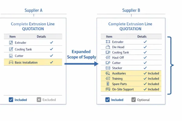
Extrusion Line Quotation: What Is Included and What to Check Before You Buy
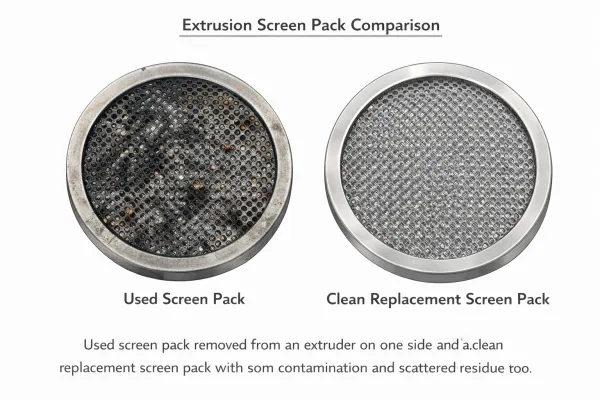
Comparing extrusion line quotations? Use this scope of supply checklist to see what is included, what is typically excluded, and…Extrusion Screen Changer & Melt Filtration: How to Reduce Contamination and Pressure Fluctuation
A practical guide to screen changers in plastic extrusion — how melt filtration controls contamination, why screen changes cause pressure…