Extrusion Line Alignment: How to Check and Correct Centerline Accuracy from Die to Cutter
Extrusion line alignment — the geometric accuracy of the centerline from the die exit through every downstream station — is one of the most overlooked causes of persistent product defects on a plastic extrusion line.
When pipe or profile keeps bending in the same direction, when wall thickness stays heavier on one side, or when haul-off pads always wear unevenly, most factories start by adjusting temperatures, screw speed, vacuum level, or haul-off speed. Sometimes that helps. But if the physical centerline of the line is already off, process adjustment can only compensate so far. The root cause is geometric, not thermal.
A small offset does not need to look dramatic to create real problems. A 1–2 mm deviation at one station may seem harmless when viewed locally. But once that offset applies a steady side force over several meters of cooling and pulling distance, the effect accumulates and becomes visible in the product. The line may still run, but it runs with a built-in mechanical bias that no amount of parameter tuning can fully remove.
This guide explains why extrusion line alignment matters, how different misalignment patterns affect product quality and equipment wear, what tools can be used to check alignment, and how to correct centerline accuracy step by step from the die to the cutter.

Why Alignment Matters More Than Most Operators Think
Misalignment is not the same as a broken machine. It is more subtle than that.
What misalignment does is apply a small but continuous lateral or angular force to a product that is still soft, still stabilizing, or still being guided into downstream equipment. That force may begin close to the die, at the calibration section, or at the haul-off entry. Wherever it begins, the result is the same: the product is no longer allowed to move through the line on a true centerline.
Product bending and twisting
The most obvious result of poor alignment is that the product bends, bows, or twists.
If downstream equipment is offset from the die centerline, the product is pulled away from its natural path. In pipe extrusion, that often appears as consistent bending toward one side. In profile extrusion, it may appear as bowing, twist, or a shape that refuses to remain straight after cooling.
This is especially critical near the calibration section. At that point, the melt has left the die but has not yet fully stabilized. Even a small directional error there — as little as 0.5 mm — can influence the shape over the entire downstream length.
Wall thickness eccentricity and ovality
Alignment problems can also create dimensional defects, not just visible bending.
If the haul-off is not centered relative to the die, the product may be pulled unevenly as it exits. That contributes to one side being stretched more than the other, especially when the product is still hot and dimensionally unstable. In pipe production, poor entry alignment into the calibration sleeve causes uneven contact with the sleeve wall, which produces ovality or persistent wall-thickness imbalance.
When that happens, operators often chase process settings first. But if the eccentricity direction is always the same — always heavier on the left, or always oval in the same orientation — line geometry must be checked before anything else. This is closely related to the wall-thickness problems discussed in Extrusion Wall Thickness Variation: Causes, Diagnosis, and Quick Fixes.
Accelerated equipment wear
Misalignment does not only affect the product. It shortens equipment life.
A calibration sleeve wears more on one side. Haul-off belts or pads show uneven contact and uneven wear. Cutter clamps stop centering the product properly. Once that wear pattern develops, the worn component makes alignment worse, and the worsened alignment accelerates wear further. This is a self-reinforcing cycle: a small setup error becomes a long-term maintenance problem that gets progressively harder to fix.
Common Misalignment Patterns and What They Cause

To diagnose alignment problems, it helps to think in patterns. Different types of misalignment create different product symptoms.
Horizontal offset
A horizontal offset means one station sits too far left or right relative to the true line center.
This typically causes the product to bend consistently toward one side. In pipe and tubing, it may also contribute to left-right wall thickness imbalance. Because the product is being guided off-center, the line develops a steady lateral bias that shows up as a repeatable directional defect.
Vertical offset
A vertical offset means one station sits too high or too low relative to the reference centerline.
This may cause the product to bow upward or sag downward, especially when the product remains soft over a long cooling path. It can also show up as uneven wear on the top or bottom contact surfaces of the haul-off.
Vertical misalignment is the easiest type to miss. A height difference of 1–2 mm is difficult to judge by eye, especially on long lines. A line can look visually straight from the side and still be vertically wrong by enough to affect product straightness.
Angular misalignment (yaw and pitch)
Angular misalignment is different from simple offset. The equipment center may appear to be in the correct location, but the machine itself is not facing the correct direction.
This is most common at the haul-off. The entry point may sit near the centerline, but if the pulling direction is slightly yawed (rotated horizontally) or pitched (tilted vertically) relative to the product path, the product enters under torsion or side load. That can create twist, spiral marking, or bending that seems difficult to explain through normal process variables.
Combined misalignment
In real factories, pure single-direction misalignment is uncommon. A line is more likely to be slightly left, slightly low, and slightly angled at the same time.
That is why visual judgment alone is unreliable for formal alignment work. The product symptom reflects the combined effect of several small errors rather than one large obvious one. Diagnosing which station is responsible requires measurement, not observation.
Tools for Checking Extrusion Line Alignment

The right tool depends on line length, required precision, and whether you are performing a routine check or a full correction.
Basic tools for routine checking
For day-to-day maintenance and lines under roughly 15 meters total downstream length, basic tools are enough for most practical alignment checks.
A plumb bob establishes vertical reference at each station. A precision spirit level (sensitivity of 0.02 mm/m or better) verifies that each machine frame is level before centerline adjustments begin — because adjusting the centerline of a machine that is not level makes no sense. A taut string line or piano wire can be run from the die center through the downstream stations to create a physical reference centerline.
For the string line method:
- Use thin, non-stretch line — piano wire (0.3–0.5 mm diameter) is best
- Apply consistent tension with a small weight or spring-loaded anchor at the far end
- Keep the line at the exact height of the die center — use a measured standoff if needed
- Check each station’s center position against this line with a ruler or caliper
This method is inexpensive, widely understood, and effective for many lines. Its main limitation is precision over distance: on lines longer than 15 meters, string sag and vibration make it difficult to hold accuracy below about ±1 mm.
Laser alignment systems
For long lines, high-precision products, new installations, or recurring problems that resist explanation, a laser alignment system is the better choice.
Laser tools maintain accuracy over distance — typically ±0.1 mm/m or better — and can detect offsets that are impossible to judge with a string line. They are especially useful on pipe extrusion lines longer than 15 meters, on lines producing products with tight dimensional tolerances, or when a line continues to show bending or eccentricity after routine process adjustments have been exhausted.
A laser system is not necessary for every correction. But for new-line commissioning, annual full-line verification, or persistent unexplained geometry problems, it is the correct tool.
Step-by-Step Extrusion Line Alignment Procedure

Alignment must be done in sequence from the die outward. If the reference point is wrong, every downstream correction becomes meaningless.
Step 1: Establish the die exit center
The die exit center is the reference point for the entire line. The importance of this reference extends back to the extruder barrel itself — if the barrel-to-gearbox alignment is off, the die center inherits that error.
Before checking anything downstream, confirm that the die itself is installed correctly:
- Verify the die is centered on the barrel adapter (check gap uniformity around the flange)
- Use a spirit level on the die face to confirm it is level (for pipe dies) or correctly oriented (for profile dies)
- Mark the true geometric center of the die exit opening — on pipe dies, this is the center of the annular gap; on profile dies, use the centroid of the flow channel opening
Every other station will be referenced back to this point. If the die is mounted off-center or tilted, the entire downstream alignment inherits that error.
Step 2: Run the reference centerline
Once the die center is established, create the reference line.
Set the string line or laser at the exact height and position of the die center, extending through all downstream stations. This line represents the geometric path that the product should follow.
The purpose is straightforward: downstream equipment aligns to this reference — not to the floor edge, not to the wall, and not to visual estimation.
Step 3: Align the vacuum calibration tank
The vacuum calibration tank is the most critical downstream station for alignment because it sits closest to the die, where the product is still soft and most sensitive to side force.
Adjust the tank height and lateral position so that both the entry and exit centers line up with the reference. Most calibration tanks have adjustable leveling feet and lateral adjustment screws — use them in small increments, checking against the reference after each adjustment.
Important: do not assume the tank frame center and the calibration sleeve center are the same. The sleeve sits inside the tank and may be offset from the frame. Check the actual working center of the sleeve or calibration tooling — that is what the product contacts, not the tank shell.
If the product enters the calibration section off-center, both dimensional problems and bending follow immediately. For broader station-based diagnosis of calibration and cooling issues, see Extrusion Troubleshooting by Station.
Step 4: Align the cooling tanks
After the calibration tank, check all cooling tanks and intermediate support points.
Each tank should guide the product along the same centerline. The rollers, guides, and support points should not force the product to change direction between stations. Pay particular attention to the transitions between tanks — a directional change at the handoff between two tanks may not be visible when looking at each tank individually, but it still imposes a side force on the product.
If the product path includes a slight zigzag through the cooling section, bending will develop over the full downstream length even though each individual tank appears aligned when viewed alone.
Step 5: Align the haul-off
The haul-off must be centered correctly, but center position alone is not enough.
Its pulling direction must also match the actual product path. A haul-off that is centered but slightly rotated (yawed) can still apply side load or torsion to the product. This is one of the most common alignment mistakes in practice.
Check three things:
- Center height — the midpoint between the upper and lower belts or pads should match the reference line height
- Left-right position — the product should enter centered between the belts, not biased to one side
- Entry direction — the product should enter straight into the haul-off, not be redirected at the last moment by the belts or pads. If the product has to “find its way in,” alignment is not correct.
Step 6: Align the cutter
The cutter should follow the same centerline.
Its center must line up with the product path, and the cutting plane must be perpendicular to the product axis. If the cutter is misaligned, the result may be angled cuts, poor clamp centering, or inconsistent cut-end presentation.
A cutter problem is sometimes treated as a cutter-only issue. But if upstream alignment is wrong, the cutter may simply be the first station where the accumulated error becomes obvious.
Step 7: Final verification
After adjustment, verify the line from both ends.
Reverse sighting is useful: stand at the downstream end and look back through the stations toward the die. Check whether the equipment really sits on one straight path. If a laser system is used, confirm that all targets remain within tolerance.
Then run product and observe the result. Alignment is not fully verified until the line produces straight, dimensionally stable product without built-in directional bias. Measure wall thickness at multiple points around the circumference (for pipe) or check profile straightness over a 1–2 meter length to confirm the improvement.
When to Realign
Full alignment does not need to be performed every day. But the following signals mean it should be checked:
- Persistent bending in one direction that cannot be corrected through normal process adjustment
- Wall-thickness eccentricity with a fixed orientation — always heavier on the same side, not random
- Uneven wear on haul-off pads, calibration sleeves, or cutter clamps — consistently worse on one side
- Equipment has been moved — for repair, relocation, or floor work near the installation base
- Floor settlement — common in older factories, especially on long lines. Concrete floors can settle unevenly over years, gradually shifting machine positions
- Die or calibration sleeve replacement — changing the die or sleeve can shift the working centerline enough to require re-verification
- Annual scheduled check — include a full-line alignment verification as part of your annual maintenance program, not just emergency troubleshooting
This connects directly to the broader extrusion line maintenance checklist, which includes line alignment as a recommended annual verification item.
Common Alignment Mistakes
Aligning center points but ignoring direction. A station may appear centered while still being rotated slightly relative to the true line path. Center position and facing direction are two separate checks.
Checking horizontal but ignoring vertical. Small height errors are hard to judge by eye but still large enough to affect the product. Always check both planes.
Assuming product bend direction directly identifies the misalignment location. Product behavior depends on where in the line the error occurs, not just the direction. A leftward bend does not necessarily mean the left-most station is wrong — it may be caused by an offset at the calibration tank that propagates downstream.
Failing to lock machines after adjustment. If leveling feet, hold-down bolts, or locking features are not properly secured, vibration and normal operation will gradually shift the machine back out of position. The correction will not last.
Aligning to the floor or wall instead of to the die center. Factory floors are not perfectly flat or straight. The reference must always be the die exit center, not any building feature.
Conclusion
Extrusion line alignment is one of those maintenance tasks that can solve long-standing problems without changing a single process setpoint.
Many recurring bending, eccentricity, and uneven wear problems do not begin in the temperature profile or the screw speed. They begin on the floor, in the physical relationship between the die and the downstream stations.
When the line is geometrically correct, process optimization becomes meaningful. When the line is geometrically wrong, process adjustment can only compensate so far — and the compensation creates its own secondary problems.
If your extrusion line has persistent bending, fixed-direction eccentricity, or recurring uneven downstream wear, line alignment should be checked before further process troubleshooting. For a structured approach to diagnosing production problems, see our Plastic Extrusion Troubleshooting guide. If you need hands-on alignment support, contact our engineering team.
Frequently Asked Questions
Q1: How accurate does extrusion line alignment need to be?
For most pipe and profile extrusion lines, the target is to keep each station within ±0.5 mm of the reference centerline in both the horizontal and vertical planes. Lines producing products with tight dimensional tolerances — such as medical tubing or optical profiles — may need tighter control. On long lines (20+ meters of downstream equipment), even ±0.5 mm per station can accumulate, so consistent accuracy at every station matters more than perfection at any single one.
Q2: Can I check alignment while the line is running?
You can make useful observations while the line runs — watch how the product tracks into the calibration tank, whether it enters the haul-off straight, and whether the cutter clamps center properly. These observations can identify which station to investigate. But formal measurement and correction should be done with the line stopped so that reference tools can be set accurately and machines can be adjusted safely.
Q3: How long does a full line alignment take?
For a typical pipe or profile extrusion line with 4–6 downstream stations, a full check-and-correct using a string line takes roughly 2–4 hours. Using a laser system is faster for the measurement phase but may require similar time for physical adjustments. A quick visual check and spot-measurement of the most critical stations (calibration tank and haul-off) can be done in under an hour.
Q4: Does floor condition affect extrusion line alignment?
Yes, significantly. Concrete floors settle over time, especially in factories with heavy equipment or where the subsoil is not fully compacted. On a 20-meter line, uneven settlement of just a few millimeters can produce measurable centerline deviation. After any floor repair, grinding, or construction near the line, alignment should be re-verified.
Q5: Should I realign after replacing a calibration sleeve or die?
Yes — or at the very least, verify alignment at that section before resuming production. A new die may have slightly different mounting geometry than the old one. A new calibration sleeve may sit differently inside the tank. These changes can shift the working centerline by enough to affect product straightness and wall-thickness distribution.
Have Technical Questions?
Our engineering team is ready to help with your extrusion process or machine configuration.
Jason Shen
Jason is the founder of Jinxin Extruder and a veteran engineer with over 20 years of hands-on experience in plastic machinery.
Starting his career on the shop floor, he mastered every technical detail—from electrical wiring to complex troubleshooting.
Today, he personally oversees final inspections, ensuring every machine is built with deep technical expertise and field-tested reliability.
Further Reading
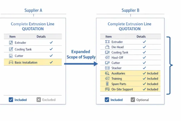
Extrusion Line Quotation: What Is Included and What to Check Before You Buy
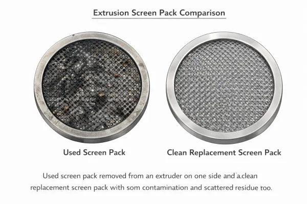
Comparing extrusion line quotations? Use this scope of supply checklist to see what is included, what is typically excluded, and…Extrusion Screen Changer & Melt Filtration: How to Reduce Contamination and Pressure Fluctuation
A practical guide to screen changers in plastic extrusion — how melt filtration controls contamination, why screen changes cause pressure…