Downstream Equipment in Plastic Extrusion: What Each Machine Does
The Extruder Only Completes Half the Job
Downstream equipment in plastic extrusion is everything that comes after the die — the set of machines that turn a hot, soft, shapeless melt stream into a finished product with precise dimensions, stable geometry, and a usable delivery form.
If you are new to extrusion, it is easy to assume that the extruder is the whole line. It melts the material, pressurizes it, and pushes it through a die to create a cross-sectional shape. But what comes out of the die is not a finished pipe, profile, or tube. It is still hot, pliable, and dimensionally unstable. At that moment, any external force — gravity, uneven airflow, even the product’s own weight — can change its shape.
The downstream system is what prevents that. Every station after the die — sizing, cooling, haul-off, and cutting — solves a specific problem that the extruder cannot solve on its own. The final product’s dimensional accuracy, roundness, straightness, wall thickness consistency, and cut quality are all determined by the downstream system, not by the extruder.
If you are not yet familiar with how the extruder itself works — how raw material is melted, compressed, and pushed through a die — read What Is a Plastic Extruder Machine? first.
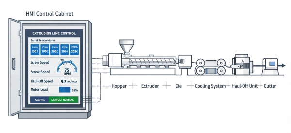
A useful way to think about a plastic extrusion line is to divide it into two halves. The first half — the extruder and die — creates a controlled melt flow and delivers it in the intended cross-sectional shape. The second half — the downstream system — keeps that hot shape from collapsing, drifting, stretching, or shrinking unevenly before it becomes a usable product. In practical terms, the downstream line must do four things in sequence: lock the shape, cool the product, pull it at a controlled speed, and cut or wind it into saleable form.
Once you see the line this way, many common quality problems become easier to trace. A product can leave the die looking correct and still end up out of round, bowed, or dimensionally unstable — if the downstream side is not doing its job.
Station 1 — Sizing and Calibration: From Soft Melt to Fixed Shape
The material leaving the die has a cross-sectional shape, but that shape is not yet locked in. The extrudate is hot, pliable, and easily deformed. The sizing station’s job is to freeze the dimensions before anything can distort them.
How this works depends on the product type.
Pipe and Tube Sizing — Vacuum Calibration Tank
For pipes and tubes, the soft tube emerging from the die enters a sealed vacuum calibration tank. Inside the tank, negative pressure pulls the soft pipe wall outward against a precision-machined calibration sleeve — a metal ring that defines the exact outer diameter. Simultaneously, circulating water rapidly cools the outer wall, hardening it while the vacuum holds the shape in place.

The calibration sleeve and the die must be precisely aligned. On most vacuum tanks, the sleeve position is adjustable on three axes — horizontal, vertical, and along the line direction — to ensure the pipe enters dead center. Misalignment creates uneven wall contact, which leads to uneven wall thickness or ovality.
If vacuum is insufficient, the pipe wall does not press tightly enough against the sleeve — the OD comes out undersized or out of round. If the sleeve itself is worn or poorly finished, every meter of pipe carries that imperfection.
Profile Sizing — Dry Calibration Blocks
For profiles (window frames, cable trunking, decorative trims), the extruded profile passes through a series of dry calibration blocks — precision metal tooling with vacuum channels that gently hold the profile surfaces against the block while spray cooling solidifies the outer skin.
The speed at which the profile moves through the calibration block matters. Too fast, and the profile does not have enough contact time with the block — dimensions drift. Too slow, and the material can stick or drag.
For simpler, solid, or very flexible profiles (such as TPU seals), a different approach is used: the extrudate passes directly into a water bath without a rigid sizing tool. This is called free sizing, and it relies on the cooling water alone to stabilize the shape. It works when tight dimensional tolerances are not required or when the material is too soft and flexible to pass through rigid tooling without friction damage.
A buyer-relevant point: the calibration sleeve (for pipes) or calibration block (for profiles) is precision tooling whose surface finish and dimensional accuracy directly determine the product’s OD tolerance. When you change product specifications, you change these tools — and they represent a significant portion of downstream tooling cost.
The sizing station is where final dimensions are formed. It is the first quality gate in the downstream system. You can cool a distorted shape, but you cannot cool it back into the correct shape.
Station 2 — Cooling: Eliminating Internal Stress and Preventing Post-Line Deformation
After the sizing station, the product’s outer wall has hardened enough to hold its shape. But the interior is still hot. If the product leaves the line without being cooled thoroughly and uniformly, it will continue to shrink and deform after stacking, coiling, or shipping — bending, warping, or ovality that only becomes visible hours later.
The extrusion cooling tank — typically a series of water-filled troughs positioned after the sizing station — is where this internal heat is removed. The product passes through continuously, and the cooling medium gradually brings the entire cross-section to a uniform, stable temperature.
The critical factors are uniformity and time:
- Uneven cooling — caused by inconsistent water temperature, uneven spray angles, or partially blocked nozzles — means different parts of the product shrink at different rates. This creates internal stress imbalances that manifest as bowing, twisting, or cross-sectional distortion.
- Insufficient cooling time — which happens whenever line speed increases without adding cooling length — means the product exits the tank with its core still warm. It looks fine on the line, but deforms after removal.
A scenario from real production: after increasing line speed on a PPR pipe line, the pipes appeared perfectly straight coming off the cutter. But after 30 minutes of stacking, they began to bow visibly. The root cause was not the extruder or the die — the existing cooling tank length was simply no longer sufficient for the higher throughput. The internal core temperature at the tank exit was still too high for the pipe to remain dimensionally stable off the line.
A point that buyers frequently underestimate: the total length of the cooling section is one of the most important — and most overlooked — factors in extrusion line planning. From the die exit to the cutter, the total line length typically ranges from 10 to 30 meters, depending on the product specification and target line speed. During factory layout planning, customers often underestimate this number, and discover that the available floor space is too short only after the equipment arrives.
The cooling section’s capacity determines how fast the line can run. The extruder’s screw speed is not the bottleneck — the cooling length is.
Station 3 — Haul-Off: The Pacemaker of the Entire Line
Among all downstream devices, the extrusion haul-off machine is one of the most misunderstood. Many people think its job is simply to pull the product forward. Mechanically, yes. Functionally, its real job is far more important: it sets and maintains the line speed.
The extruder outputs material at a roughly constant rate. The haul-off pulls the product away from the die. The wall thickness of the product is a direct function of the ratio between these two speeds:
- Haul-off speed increases → the product is stretched → wall thickness decreases
- Haul-off speed decreases → material accumulates → wall thickness increases
Any fluctuation in haul-off speed — no matter how small — translates directly into wall thickness variation. For precision thin-wall pipes, even a fraction-of-a-percent speed wobble can push the product out of tolerance.
Common causes of haul-off instability include worn caterpillar tracks or grip pads, inconsistent clamping pressure, and drive control lag that introduces speed oscillations.
A diagnostic insight for troubleshooting: when you see a rhythmic, periodic pattern in wall thickness — thicker every few meters, then thinner, repeating — the first place to investigate is the haul-off, not the extruder. This “pulsing” pattern is a classic signature of haul-off instability and one of the most commonly misdiagnosed quality issues in pipe extrusion.
A real production case: on a pipe extrusion line, after the haul-off was replaced with a different unit, wall thickness began showing periodic fluctuations with an 8-meter cycle — down from the previous stable 20-meter measurement interval. All extruder parameters remained unchanged. The team spent two days investigating temperature profiles and screw conditions before discovering that the replacement haul-off had a slightly different PID response characteristic, causing a subtle speed oscillation invisible on the control screen but clearly measurable in the product. This kind of “equipment substitution mismatch” is a real and common hazard — a machine that works perfectly on its own may introduce system-level problems when integrated into an existing line.

When configuring a line, haul-off speed stability (closed-loop control precision) deserves more attention than pulling force — especially for thin-wall, precision pipe applications.
The haul-off is the speed reference for the entire line. Every other station must synchronize with it.
For a deeper technical look at haul-off control principles, see this overview from Plastics Technology
Station 4 — Cutting and Collection: Turning Continuous Output Into Sellable Products
Extrusion is a continuous process. Customers do not buy “continuous.” They buy cut lengths, coils, bundles, or stacks. The cutting and collection station is where the product leaves the process state and enters the delivery state — and it is not just a finishing step. The extrusion cutter determines end-face quality, and the winding system determines the form stability of coiled products.
Rigid Pipe — Planetary Cutter and Stacker
For rigid pipes (PPR, PE, PVC), the standard cutting system is a planetary cutter (also called a chipless cutter). The blade orbits around the pipe and advances inward as it rotates, producing a clean, burr-free, perpendicular cut without generating chips or dust. This matters for pipes that need to be joined by fusion welding or mechanical fittings — a rough or angled cut creates a weak joint.

After cutting, an automatic stacker (pneumatic tilting cradle) receives the cut pipe and flips it onto a collection rack, preventing end damage from impact.
Soft Tube and High-Speed Profile — Flying Knife Cutter
For small-diameter soft tubing or continuous profiles running at high speed, a flying knife cutter is used. It moves with the product at line speed and cuts on the fly, allowing very high cut frequencies without stopping or slowing the line.
Flexible Products — Tension-Controlled Coiler
For soft hoses, PE tubing, and TPE elastic bands, the product is coiled rather than cut to length. A tension-controlled coiler winds the product onto a spool or drum at consistent tension. If winding tension is uneven, the coil will have alternating tight and loose layers — causing deformation on the spool, unwinding problems for the downstream customer, and in some cases permanent stretching of elastic materials.

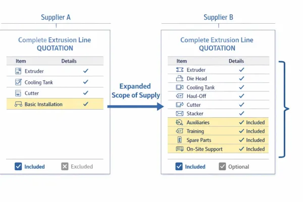
A buyer-relevant point: cutting and collection equipment varies more than any other downstream station. The choice depends entirely on the product type — rigid vs. flexible, large vs. small diameter, cut-to-length vs. coiled, and how sensitive the product is to end-face quality. This is the most application-specific part of the downstream package, and it is also the area where line quotations most commonly have missing items or mismatched specifications. Two lines may share a similar extruder and die concept while needing completely different end-of-line equipment.
The cutting and collection system directly determines the final presentation of the product. A wrong choice leads to poor end-face quality or packaging inefficiency.
Why Downstream Problems Are Often Mistaken for Extruder Problems
One of the most useful things a beginner can learn is that many product defects on an extrusion line are not caused where they first become visible:
- A pipe that comes out oval may not have a die problem — it may have lost dimensional control in the calibration or cooling zone.
- A wall thickness fluctuation may not come from unstable melt output — it may be haul-off speed variation.
- A product that looks dimensionally correct at machine exit but warps after stacking may not have a shaping issue — it may simply be undercooled.
- A poor end face may say nothing about the extruder — it may only reflect an unsuitable cutting method.
These misdiagnoses happen because people naturally look upstream — toward the biggest, most visible machine — when something goes wrong. But in reality, the downstream system is where most dimensional and stability-related quality is determined.
From Jinxin’s experience as an extrusion line manufacturer: downstream issues almost always surface during full-line commissioning, not during individual equipment acceptance testing. A vacuum tank can run. A haul-off can run. A cutter can run. That does not mean the line will run well as a synchronized system.
A haul-off that performs perfectly on its own test bench may introduce speed oscillations when integrated with a specific extruder and control system. A cooling tank that passes its standalone water flow test may prove too short for the actual target line speed.
This is the fundamental reason why FAT (Factory Acceptance Testing) should include full-line integrated operation — not just individual machine sign-off.
A Practical Way to Remember the Downstream Line
If you want a simple mental map, remember the downstream system as a four-step sequence:
Calibration locks the geometry.
Cooling stabilizes the product.
Haul-off sets the speed.
Cutting or winding defines the delivery form.
Each machine exists to solve a specific production problem. Together, they form a synchronized system where the performance of each station affects every other.
The extruder creates the melt flow. The downstream system turns that flow into a product you can measure, pack, ship, and use. To understand what a complete plastic extrusion line looks like from raw material to finished product, read What Is a Plastic Extrusion Line?
Now that you understand what each downstream station does, the next step is understanding how a complete extrusion line is configured for your specific product.
See how the extruder and downstream system come together as one integrated line: What Is a Plastic Extrusion Line?
Ready to plan a line? Share your product requirements and our engineering team will put together a full-line configuration recommendation.
Have Technical Questions?
Our engineering team is ready to help with your extrusion process or machine configuration.
Jason Shen
Jason is the founder of Jinxin Extruder and a veteran engineer with over 20 years of hands-on experience in plastic machinery.
Starting his career on the shop floor, he mastered every technical detail—from electrical wiring to complex troubleshooting.
Today, he personally oversees final inspections, ensuring every machine is built with deep technical expertise and field-tested reliability.
Further Reading
Extrusion Line Quotation: What Is Included and What to Check Before You Buy
Comparing extrusion line quotations? Use this scope of supply checklist to see what is included, what is typically excluded, and…Extrusion Screen Changer & Melt Filtration: How to Reduce Contamination and Pressure Fluctuation
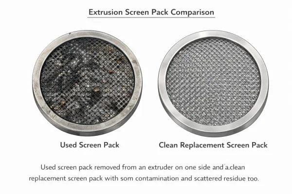
A practical guide to screen changers in plastic extrusion — how melt filtration controls contamination, why screen changes cause pressure…