Что такое экструзия пластмассы? Объяснение процесса (от плавления до охлаждения)
Написано технической командой Jinxin | Проверено Джейсоном (главным инженером)
Экструзия пластмасс - это непрерывный производственный процесс используется для производства крупносерийной продукции, такой как трубы, трубки, профили, листы, пленки и проволока/кабель с покрытием. Проще говоря, пластик расплавляют, проталкивают через фигурную умереть, и охлаждается до постоянного сечения.
Если вы впервые изучаете экструзию - особенно с точки зрения поиска поставщиков или закупок, - то главный вопрос, как правило, заключается в консистенции: Может ли процесс выдерживать размеры и качество поверхности в течение длительного времени без постоянных корректировок?
Это руководство объясняет что такое экструзия пластмассы, Как происходит процесс, шаг за шагом, и какие переменные обычно имеют значение при оценке целесообразности.

Краткое резюме
Определение: Экструзия пластика - это непрерывный процесс, в ходе которого термопластичный материал расплавляется и проходит через фильеру, образуя непрерывный профиль с постоянным поперечным сечением.
Общие выходы: Трубы, трубки, профили, листы/пленки, кабельная оболочка и другие непрерывные промышленные формы.
Что способствует стабильности: На практике на консистенцию влияет история температуры расплава, поведение давления, консистенция охлаждения и синхронизация скорости линии.
Почему покупателям это важно: Более высокая стабильность обычно означает меньшее количество брака, большую повторяемость размеров и более плавное наращивание производства.
Что такое экструзия пластмассы?
Экструзия пластмасс - это производственный процесс, в ходе которого термопластичная смола (обычно гранулы, иногда порошок или смесь) превращается в непрерывный продукт путем ее расплавления в экструдере и проталкивания расплава через фильеру. Затем экструдат охлаждается, вытягивается с контролируемой скоростью и разрезается или наматывается на готовые изделия.
Экструзия и литье под давлением (быстрая разница)
Экструзия: Непрерывная производительность для изделий с постоянным сечением (трубы, трубки, профили, листы/пленка).
Литье под давлением: Циклический вывод для дискретных 3D-деталей (крышки, корпуса, сложные компоненты).
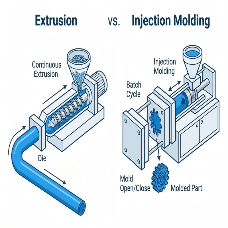
Понимание фундаментальных различий между экструзией и литьем под давлением поможет выбрать правильный процесс для ваших производственных нужд:
| Характеристика | Экструзия пластмассы | Литье под давлением |
|---|---|---|
| Тип процесса | Непрерывный | Партия |
| Форма изделия | Равномерное поперечное сечение (2D) | Сложные 3D-формы |
| Объем производства | Большие объемы непрерывной работы | Отдельные детали в партиях |
| Затраты на оснастку | Снижение стоимости штампа | Более высокая стоимость пресс-формы |
| Материальные отходы | Минимум отходов | Бегуны и ворота создают отходы |
| Типичные продукты | Трубы, профили, листы, пленки | Контейнеры, детали, корпуса |
| Точный контроль | Критично для стабильности размеров | Критично для детализации |
Как работает процесс экструзии пластмассы (шаг за шагом)
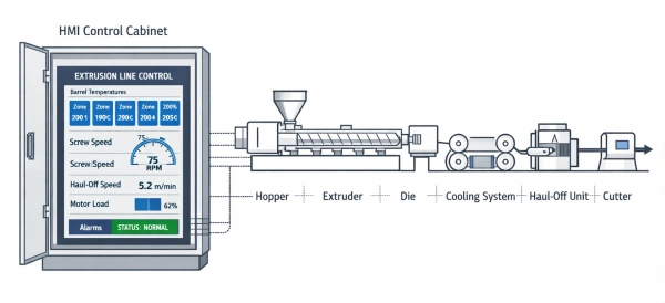
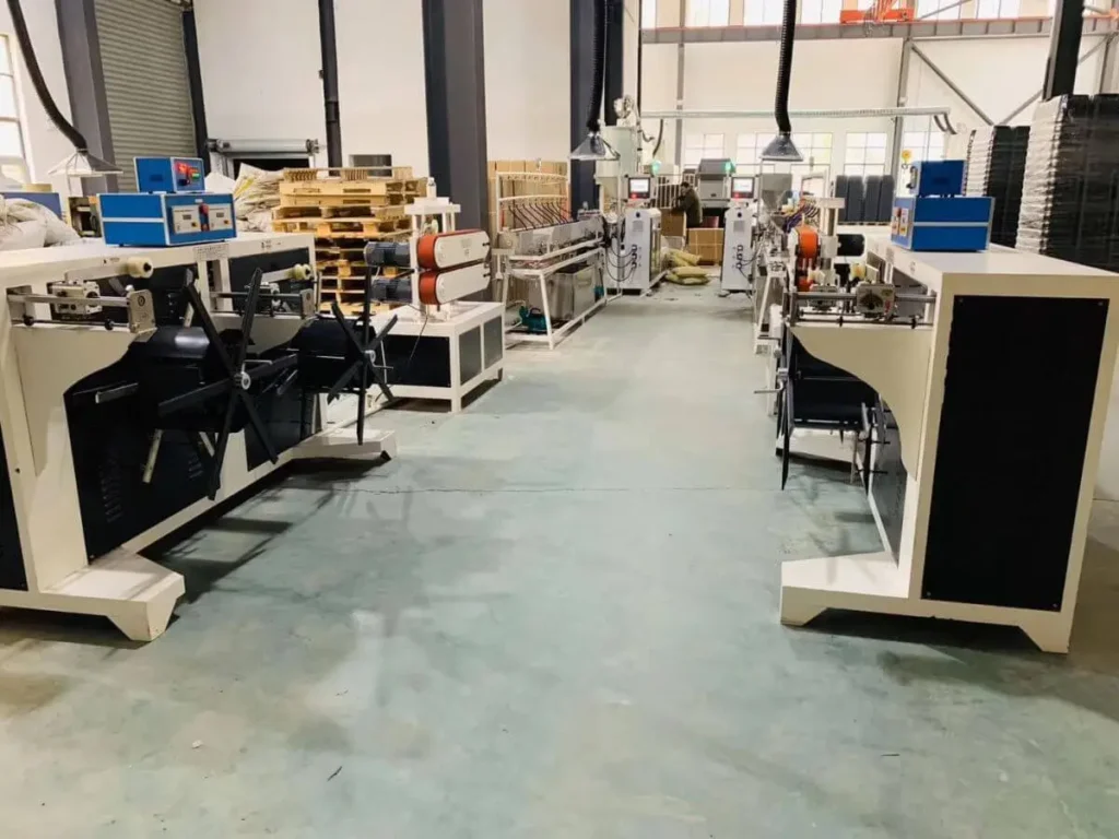
Примечание: Этот раздел посвящен экструзии пластмасс как процессу - тому, что происходит с материалом во время плавления, формовки и охлаждения. A “линия экструзии пластмасс” - это комплектация оборудования (экструдер, фильера, охлаждение/размер, транспортировка, резка/намотка). Если вы сравниваете конфигурации линий или их площадь, об этом лучше рассказать в отдельном руководстве по экструзионным линиям - “Что такое экструзионная линия для пластика”.
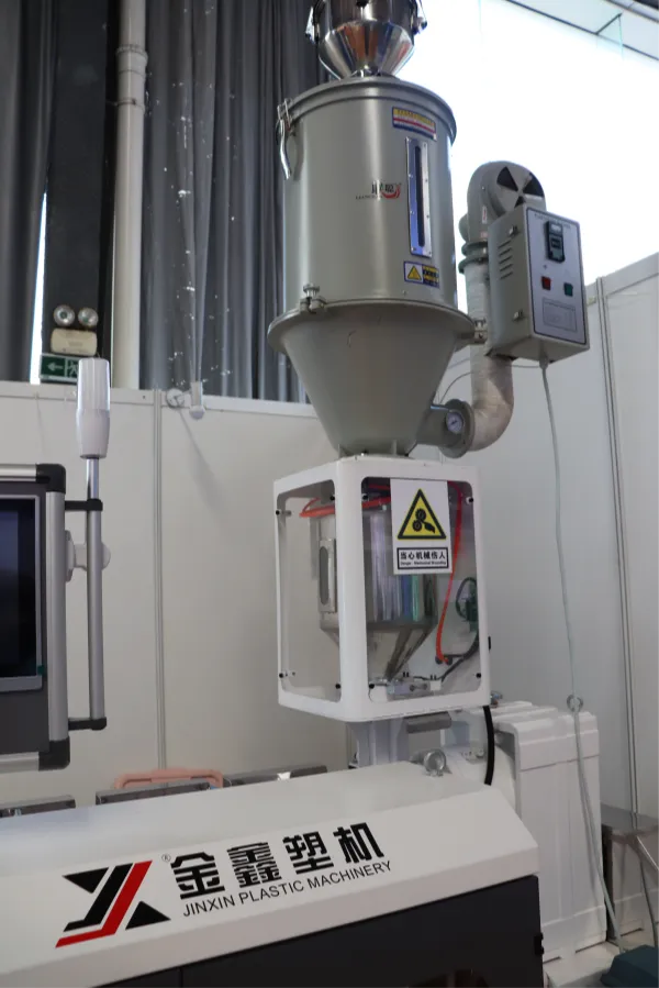
Шаг 1 - Кормление (стабильное поступление задает исходный уровень)
Процесс начинается в бункере. Материал вводится в экструдер, и целью является стабильная, повторяющаяся подача. Если подача происходит непоследовательно (например, перекрытие, загрязнение или плохое обращение с материалом), При этом остальной процесс часто становится сложнее стабилизировать.
С точки зрения покупателя, это может проявляться в нестабильной производительности, частых перенастройках и большем количестве пусковых отходов - даже если сам экструдер исправен.
Этап 2 - плавление и транспортировка (получение однородного расплава)
Внутри бочки вращающийся шнек подает материал вперед, нагревая и перемешивая его. Подробнее о том, как конструкция винтов влияет на это, см. [→ Что такое машина для экструзии пластмасс?] Плавление происходит за счет сочетания нагрева бочки и механической энергии, возникающей при вращении шнека (сдвиг). На практике целью является не только “полное расплавление”, но и достаточно однородный (температура и консистенция смеси) для уменьшения разброса по потоку.
Полезной мысленной моделью является то, что шнек выполняет сразу несколько задач: транспортирует твердые частицы, плавит, смешивает и создает давление. Если какая-либо из этих функций становится нестабильной, это часто проявляется в виде дефектов поверхности или смещения размеров.

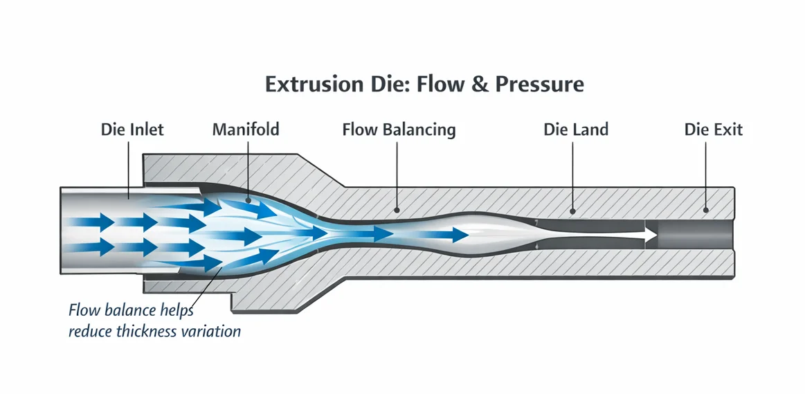
Шаг 3 - Формирование штампа (расход и давление)
Штамп - это связующее звено между машиной и изделием. На практике он выполняет две задачи:
- Формирование: Он преобразует расплав из отверстия экструдера в целевое сечение (например, кольцевую трубу, профиль или лист).
- Сопротивление потоку (напор): Ограничивая поток, фильера создает сопротивление, которое помогает стабилизировать подачу расплава и способствует более равномерному плавлению/смешиванию в верхней части линии - в сочетании с правильной конструкцией шнека и контролем температуры.
Хорошо продуманный штамп также помогает выпрямить и сбалансировать поток чтобы расплав выходил равномерно по всему сечению. Если баланс потока нарушен, вы можете наблюдать линии потеков, неравномерную толщину или нестабильный выход.
Примечание: Форма, выходящая из штампа, является лишь отправной точкой. Окончательные размеры устанавливаются на следующих этапах.
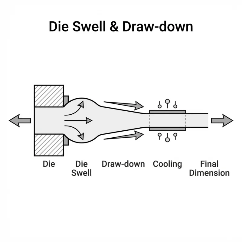
Шаг 4 - Разбухание и затягивание кубика (почему кубик редко совпадает 1:1)
Даже при использовании хорошо изготовленной фильеры экструдат редко сохраняет точную форму выхода из фильеры. Несколько эффектов действуют в разных направлениях:
- Разбухать (расширяться): Расплавы полимеров могут расслабляться и расширяться после выхода из фильеры высокого давления.
- Стягивание (сокращение): Во многих изделиях тяга происходит быстрее, чем расплав выходит из фильеры, в результате чего профиль становится тоньше/меньше.
- Термическая усадка: При охлаждении изделие, как правило, еще больше усаживается, в зависимости от смолы и условий охлаждения.
Из-за этих комбинированных эффектов штамповая оснастка часто проектируется с компенсацией чтобы охлажденный продукт попал в заданное измерение.
Практический вывод: Штамп задает концепцию поперечного сечения, но окончательные размеры обычно подгоняются с помощью скорость транспортировки и консистенция охлаждения, При этом контролируются размеры и тенденции процесса.
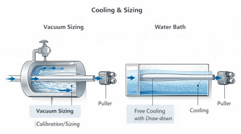
Шаг 5 - Охлаждение и определение размеров (размеры замка)
Охлаждение - это тот момент, когда форма становится “реальной”. В зависимости от типа изделия и его жесткости охлаждение может включать в себя охлаждение в водяной бане, воздушное охлаждение и/или калибровочные и размерные инструменты. Для многих жестких труб и трубок, определение размеров/калибровка вакуума обычно используется для контроля внешнего диаметра и округлости. Для других изделий может быть достаточно естественного охлаждения с контролируемой вытяжкой.
Последовательность охлаждения имеет значение, поскольку неравномерное охлаждение может привести к овальности, короблению или внутреннему напряжению - особенно при изменении скорости линии или нестабильной температуре/потоке воды.
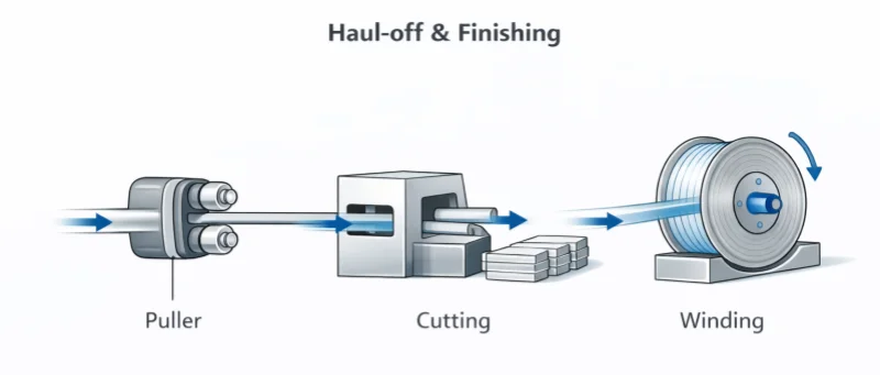
Этап 6 - Отвод и завершение (синхронизация линии)
Тянущее устройство задает скорость линии и влияет на протяжку. Резка или намотка превращает непрерывную продукцию в рулоны или отрезки, пригодные для продажи. Если скорость тянущего устройства и подача расплава не синхронизированы, вы можете наблюдать смещение толщины стенки, нестабильность OD или несоответствующий внешний вид поверхности.
С точки зрения покупателя, именно здесь важен “весь процесс”: производительность экструзии, охлаждение и стабильность вытягивания - все взаимосвязано.
Основные переменные, которые обычно контролируют стабильность
1) История температуры расплава (не только уставки нагревателя)
Температура расплава - это нечто большее, чем заданные значения для бочек. На практике температура расплава может меняться в зависимости от скорости вращения шнека, нагрузки, противодавления и поведения материала. Изменение температуры расплава может повлиять на консистенцию потока, внешний вид поверхности и повторяемость размеров.
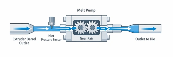
2) Поведение давления (практический показатель, за которым следят многие операторы)
Многие команды отслеживают динамику давления в расплаве/ фильере как практический показатель стабильности, особенно при диагностике скачков или смещения выхода. Поведение давления часто обсуждается при поиске и устранении неисправностей экструзии, поскольку оно может коррелировать с изменениями в консистенции выпускаемой продукции.
3) Синхронизация скорости линии (выходной сигнал зависит от скорости съемника)
Экструзия непрерывна, но это не “установил и забыл”. Если скорость съемника меняется, а подача и охлаждение расплава не успевают за ней, продукт может растягиваться, утолщаться или смещаться. При длительной работе небольшие нестабильности скорости могут накапливаться и превращаться в ощутимые отклонения.
Общие проблемы экструзии пластмасс (вид процесса)
Таблица быстрого поиска и устранения неисправностей
| Дефект | Что вы видите | Вероятные движущие силы процесса | Практические проверки (первая сдача) |
|---|---|---|---|
| Наплывы / смещение толщины | Циклическое изменение OD/стенки | Непостоянное кормление, нестабильное поведение при надавливании, непостоянство таяния | проверить стабильность бункера/подачи; проанализировать динамику давления; стабилизировать состояние расплава |
| Шероховатая поверхность (акулья кожа/расплав) | шероховатая или матовая текстура | высокий уровень сдвига на выходе из фильеры, нарушение температурного баланса | уменьшите скорость сдвига (об/мин); проверьте температурный баланс матрицы; проверьте состояние поверхности матрицы |
| Овальность (трубы/трубочки) | продукт не круглый | Неравномерное охлаждение/размер | сбалансировать охлаждающую воду; проверить условия определения размеров (если используются); проверить выравнивание/опору ниже по течению |
| Пузырьки/пустоты | отверстия/пустоты внутри стены | влажность/воздух/загрязнение (в зависимости от материала) | проверить стратегию обращения с материалом/сушки; проверить наличие уноса воздуха |
| Обесцвечивание / пятна от ожогов | черные точки, пожелтение | деградация, мертвые зоны, загрязнение | уменьшение времени пребывания; очистка фильеры; проверка на наличие застойных зон и источников загрязнения |
Краткий пример точности
Некоторые приложения менее снисходительны: небольшие колебания могут стать заметным браком. Одним из примеров является Прозрачные трубчатые преформы на основе PS, используемые в производстве некоторых лабораторных расходных материалов, В этом случае внешний вид и консистенция могут быть чувствительны к нестабильным условиям расплава и смещению скорости линии.
Этот пример приведен лишь для того, чтобы проиллюстрировать общий принцип: при ужесточении требований к консистенции команды, как правило, больше полагаются на стабильные условия расплава, дисциплинированную синхронизацию линий и повторяющееся охлаждение - независимо от категории смолы.
Если вы подбираете экструдер (что нужно подготовить перед запросом котировок)
Команды, занимающиеся закупками, обычно получают более быстрые и сопоставимые предложения при подготовке:
- Чертеж или образец изделия (какие размеры и характеристики имеют наибольшее значение)
- Основные характеристики смолы (гранулы/порошок/смесь; наполнители/пластификаторы/мастербатч; степень измельчения)
- Заданная производительность (кг/ч или м/мин) и ожидаемое время работы
- Приоритеты качества (повторяемость размеров, чистота поверхности, предельная овальность, допуск на брак)
- Предпочтения по нисходящей линии (подход к охлаждению, тип съемника, резка и намотка)
Для структурированного процесса RFQ вы можете отправить эти данные с помощью формы на нашем сайте Контакты страница.
Заключение
Что такое экструзия пластмассы в реальном производстве? Это непрерывный процесс, в котором стабильность обычно определяет рентабельность: стабильная подача, равномерное плавление, предсказуемое поведение давления, последовательное охлаждение и синхронная отгрузка.
Если вы сравниваете поставщиков или системы, оцените, как каждый подход поддерживает стабильную работу, а не только пиковую производительность.
Часто задаваемые вопросы
Вопрос 1: Что такое экструзия пластмассы и как она работает?
О: Экструзия пластмасс - это непрерывный производственный процесс, в ходе которого расплавляется термопластичная смола (обычно гранулы) и проталкивается через фильеру для создания изделий с постоянным поперечным сечением. Процесс включает в себя подачу материала в нагретую бочку, плавление и подачу его с помощью вращающегося шнека, формование расплава через фильеру, охлаждение экструдата и его вытягивание с контролируемой скоростью перед резкой или намоткой.
Вопрос 2: В чем разница между экструзией и литьем под давлением?
О: Экструзия позволяет получать непрерывные изделия с однородным сечением (трубы, трубки, профили, листы), в то время как литье под давлением создает дискретные 3D-детали в циклах (крышки, корпуса, контейнеры). При экструзии используются более дешевые фильеры и образуется минимум отходов, в то время как при литье под давлением требуются более дорогие пресс-формы, и в качестве отходов образуются бегуны/затворы.
Вопрос 3: Что вызывает разбухание фильеры при экструзии пластмасс?
О: Разбухание фильеры происходит, когда расплав полимера расслабляется и расширяется после выхода из фильеры высокого давления. Это нормальный эффект упругого восстановления полимерных расплавов. Для достижения заданных размеров штамповая оснастка обычно проектируется с компенсацией (меньше конечного размера) для учета разбухания штампа, утяжки от скорости вытягивания и термической усадки при охлаждении.
Вопрос 4: Каковы наиболее распространенные дефекты при экструзии пластмасс?
О: Распространенные дефекты включают в себя: наплывы/отклонение по толщине (из-за непостоянной подачи или нестабильности расплава), шероховатая поверхность/акулья кожа (высокий сдвиг или температурный дисбаланс на выходе из фильеры), овальность (неравномерное охлаждение или условия определения размеров), пузырьки/пустоты (влага, захват воздуха или загрязнение) и обесцвечивание/ожоги (ухудшение качества из-за чрезмерного времени выдержки или мертвых зон).
Q5: Что необходимо подготовить покупателям перед тем, как приступить к выбору экструзионной линии?
О: Чтобы быстрее получить точные предложения, подготовьте: чертеж или образец изделия с указанием критических размеров и характеристик, спецификации смолы (тип гранул, наполнители, степень измельчения), целевые показатели производительности (кг/ч или м/мин) и ожидаемое время работы, приоритеты качества (повторяемость размеров, качество обработки поверхности, допуск брака) и предпочтения в отношении последующей обработки (способ охлаждения, резка против намотки).
Дальнейшее чтение
Для читателей, желающих углубиться в управление процессом экструзии и выбор оснастки:
PTOnline: Использование контроля давления для минимизации колебаний процесса при одношнековой экструзии.
PTOnline: Как выбрать правильную оснастку для экструзии труб
Изучить темы
Фильтр по характеристикам
ABS (1) Послепродажная поддержка (1) Черные пятна (2) Экструзионные фильеры (1) проблемы с кормлением (1) Намерение: Основы (10) Намерение: Контроль (3) Намерение: Техническое обслуживание (6) PA (1) ПК (1) PE (1) ПММА (1) PP (1) покупка (1) ПВХ (1) Устранение неполадок (5) изменение толщины стенки (2)
У вас есть технические вопросы?
Наша команда инженеров готова помочь вам с выбором процесса экструзии или конфигурации машины.
Джейсон Шен
Джейсон - основатель компании Jinxin Extruder и инженер-ветеран с более чем 20-летним практическим опытом работы с пластиковым оборудованием.
Начав свою карьеру в цеху, он освоил все технические детали - от электропроводки до устранения сложных неисправностей.
Сегодня он лично контролирует окончательные проверки, гарантируя, что каждая машина создана с учетом глубоких технических знаний и проверенной на практике надежности.
Дальнейшее чтение
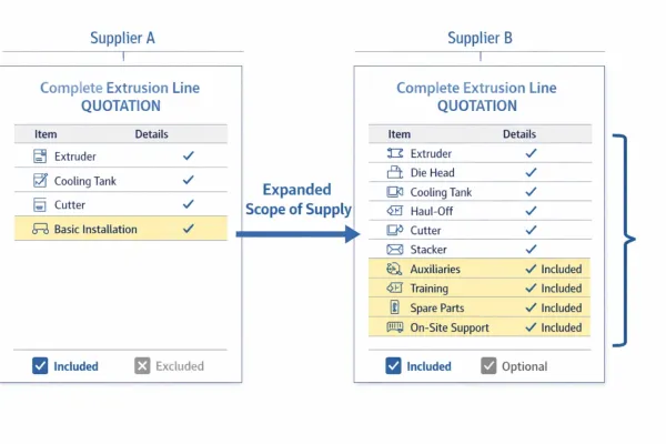
Котировка экструзионной линии: Что входит в комплект и что нужно проверить перед покупкой
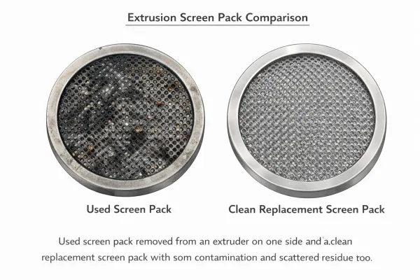
Сравниваете расценки на экструзионные линии? Воспользуйтесь этим контрольным перечнем объемов поставок, чтобы узнать, что в них входит, что обычно исключается, и...Экструзионный ситоизмельчитель и фильтрация расплава: Как уменьшить загрязнение и колебания давления
Практическое руководство по устройствам смены сит в экструзии пластмасс - как фильтрация расплава контролирует загрязнение, почему смена сит вызывает давление...